System and method for phase-readout and active stabilization of optical interferometers

a technology of optical interferometer and active stabilization, which is applied in the field of system and method for phase-readout and active stabilization of optical interferometer, can solve the problems of measurement uncertainty, reducing control, drifting and random fluctuations of interferometer phase, etc., and achieves the effect of easy separation

Active Publication Date: 2018-06-28
INSTITUT NATIONAL DE LA RECHERCHE SCIENTIFIQUE
View PDF5 Cites 12 Cited by
  • Summary
  • Abstract
  • Description
  • Claims
  • Application Information

AI Technical Summary

Benefits of technology

[0010]In order to address the above and other drawbacks, there is provided a system and method for phase-readout / control and active stabilization on arbitrary interferometric phase in the optical interferometer platform. The previous limitations are overcome by introducing a new method that makes use of a bi-colored polarization-multiplexed reference laser scheme. The disclosed scheme is based on two phase-locked reference signals with different frequencies that together remove the phase ambiguity. The two signals are polarization-multiplexed (either in free-space implementations, or using polarization-maintaining optical fibers) to enable easy separation and combining of these two signals through the use of polarization beam-splitters. The disclosed scheme provides a unique, one-to-one map between phase and feedback signal levels, and enables straightforward phase-readout and stabilization even when one of the feedback-signals is at a maximum / minimum.

Problems solved by technology

However, various environmental factors such as thermal, acoustic, and mechanical perturbations change the optical path difference between interferometer arms and cause drifts and random fluctuations in interferometer phase.
The large uncertainty in the phase reduces control over how precisely a signal can be interfered by the interferometer, introducing measurement uncertainties.
However, as the impact of environmental factors is only reduced (and not eliminated) with passive stabilization methods, these are insufficient on their own for long-term operational stability and they must usually be combined with active stabilization techniques.
Interferometer phase-readout and active stabilization methods to date have largely been limited to the use of a small phase modulation (dither) in an interferometer arm (Freschi A. A., and Frejlich J.
Additionally, the phase at readout-signal maxima / minima is difficult to precisely define as these points have a low phase derivative; a large change in phase corresponds to only a small change in the readout signal.
Phase readout and stabilization schemes that address these issues do so at the expense of reduced precision in phase control or a greatly increased setup complexity / cost.
For example, dithering adds an additional noise source that degrades output quality in applications such as quantum optics (Grassani D., Galli M., and Bajoni D.
Many stabilization methods for free-space interferometer setups allow precise phase-readout and arbitrary-phase stabilization (Grassani), but are either too complex, costly, or simply not transferable to fiber-optic interferometers (which have issues unique to the fiber platform, such as birefringence shifts in the interferometer arms).
Therefore, despite the development of phase-readout methods in optical interferometers as well as active stabilization schemes, these methods and systems are usually limited to one particular implementation and especially for fiber interferometers, several phase-readout issues still need to be addressed.
For interferometric sensing and interferometer stabilization applications, the following issues are not yet solved in all platforms: (i) intrinsic phase ambiguities due to the periodicity of feedback signals (Grassani); (ii) phase ambiguity at feedback signal extrema (it is difficult to accurately stabilize on maxima / minima due to the low signal derivative and potential sign-change of the feedback signal).

Method used


Image

  • System and method for phase-readout and active stabilization of optical interferometers
  • System and method for phase-readout and active stabilization of optical interferometers

Examples


Embodiment Construction

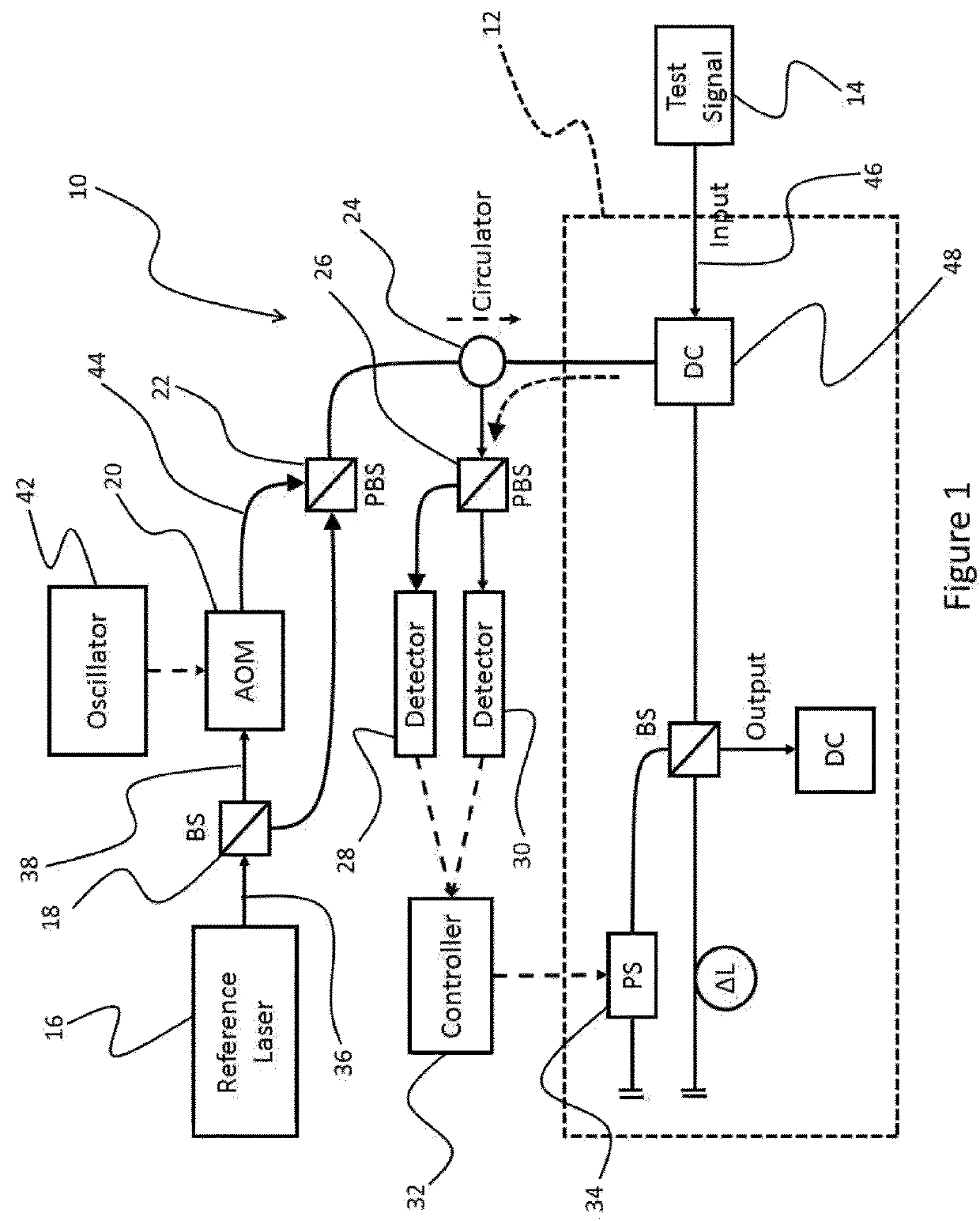
[0014]Referring now to FIG. 1, a system for stabilization at an arbitrary phase of fiber-based interferometers generally referred to using the reference numeral 10, and in accordance with an illustrative embodiment of the present invention, will now be described. The system 10 is used to first extract the exact phase, and then perform phase-stabilization of interferometer 12, illustratively an unbalanced Michelson interferometer, being used analyze a test signal 14 being input to the interferometer 12.

[0015]The system 10 comprises a light source 16, beam splitter 18, a frequency shifter 20, a first polarizing beam-splitter 22, a PM optical circulator 24, a second beam splitter 26, a first photodetector 28, a second photodetector 30 and a controller 32 which controls an adjustable phase arm 34 of interferometer 12.

[0016]In operation, the light source 16 generates a stabilized single-frequency linearly-polarized output 36 which is divided into a first signal 38 and a second signal 40 ...


PUM


Abstract

A system and method for phase-readout/control and active stabilization on arbitrary interferometric phase in the optical interferometer platform is disclosed. The method makes use of a bi-colored polarization-multiplexed reference laser scheme. The disclosed scheme is based on two phase-locked reference signals with different frequencies that together remove the phase ambiguity. The two signals are polarization-multiplexed (either in free-space or optical fiber implementations) to enable easy separation and combining of these two signals through the use of polarization beam-splitters. The disclosed scheme provides a one-to-one map between phase and feedback signal levels, and enables phase-readout and stabilization even when one of the feedback-signals is at a maximum/minimum.

Description

FIELD OF THE INVENTION[0001]The present invention relates to a system and method for phase-readout / control in the optical interferometer platform as well as a system and method for active stabilization at an arbitrary interferometric phase of fiber-based and free-space interferometers. The method and system makes use of a bi-colored polarization-multiplexed reference laser schemeBACKGROUND[0002]Interferometry is central to research and industrial applications such as high-precision metrology (Cho S.-B., and Noh T.-G. “Stabilization of a long-armed fiber-optic single-photon interferometer.” Optics express 17, no. 21 (2009): 19027-19032, incorporated herein by reference in its entirety, hereinafter Cho), optical coherence tomography (Huang D., Swanson E. A., Lin C. P., Schuman J. S., Stinson W. G., Chang W., Hee M. R., Flotte T., Gregory K., and Puliafito C. A. “Optical coherence tomography.” Science 254, no. 5035 (1991): 1178-1181, incorporated herein by reference in its entirety, he...

Claims


Application Information

Patent Timeline
Patent Type & Authority Applications(United States)
IPC IPC(8): G01B9/02G01J3/45G01J9/02
CPCG01B9/02067G01B9/02003G01B9/02027G01J3/45G01J9/02G01B2290/45G01B2290/70G01J2009/0226G01H9/004G01K11/00
Inventor ROZTOCKI, PIOTRREIMER, CHRISTIANKUES, MICHAELHELSTEN, ROBINJESTIN, YOANNMORANDOTTI, ROBERTO
Owner INSTITUT NATIONAL DE LA RECHERCHE SCIENTIFIQUE
Why Eureka
Try Eureka