Eureka AIR delivers breakthrough ideas for toughest innovation challenges, trusted by R&D personnel around the world.

Quantum interference device, atomic oscillator, and electronic apparatus

Inactive Publication Date: 2018-08-23
SEIKO EPSON CORP
View PDF3 Cites 4 Cited by
  • Summary
  • Abstract
  • Description
  • Claims
  • Application Information

AI Technical Summary

Benefits of technology

The invention provides a quantum interference device that can increase the heat resistance of an atomic cell and prevent a decrease in the intensity of an EIT signal. Additionally, it offers an atomic oscillator, an electronic apparatus, and a vehicle that use this device.

Problems solved by technology

However, when increasing the pressure of the buffer gas, the relaxation of the electron spin state due to the collision of the alkali metal with the buffer gas was increased, and as a result, the interaction time was limited, and therefore, sufficient characteristics could not be obtained.
Further, in a paraffin layer included in the gas cell described in JP-A-2013-181941, the melting point of paraffin is as low as about 70° C., and therefore, heat resistance is not sufficient.

Method used


Image

  • Quantum interference device, atomic oscillator, and electronic apparatus
  • Quantum interference device, atomic oscillator, and electronic apparatus
  • Quantum interference device, atomic oscillator, and electronic apparatus

Examples


Embodiment Construction

[0045]Hereinafter, embodiments of a quantum interference device, an atomic oscillator, an electronic apparatus, and a vehicle will be described in detail with reference to the accompanying drawings.

1. Atomic Oscillator (Quantum Interference Device)

[0046]First, an atomic oscillator according to this embodiment will be described. Hereinafter, an example in which a quantum interference device according to the embodiment is applied to an atomic oscillator will be described, however, the quantum interference device according to the embodiment is not limited thereto, and can also be applied to, for example, devices such as a magnetic sensor and a quantum memory.

[0047]First, the atomic oscillator according to the embodiment will be briefly described.

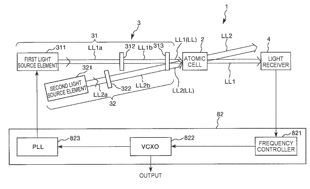
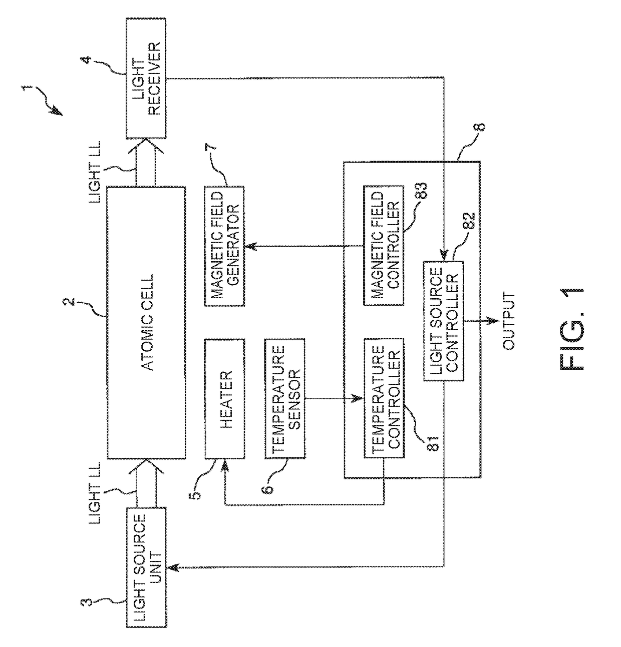
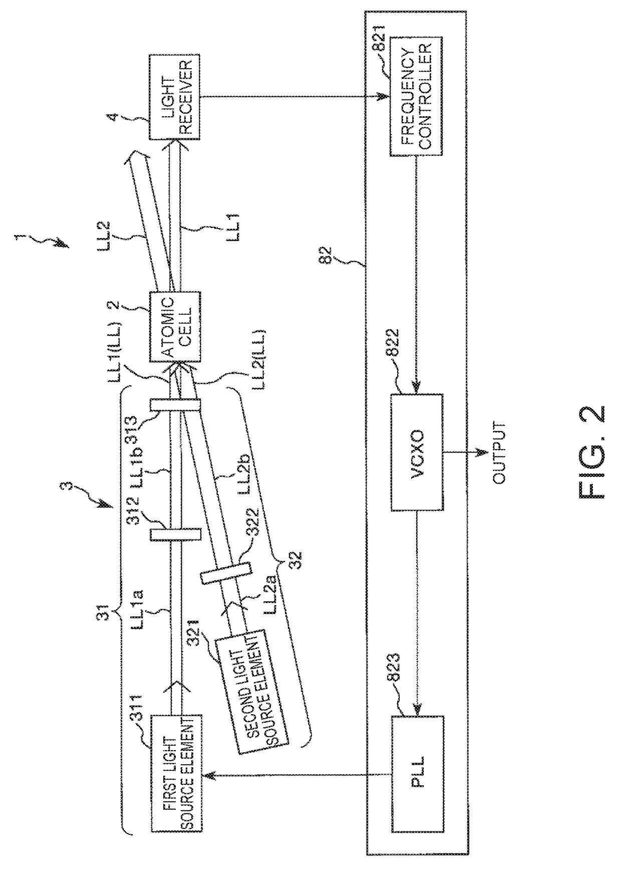
[0048]FIG. 1 is a schematic view showing an example of the atomic oscillator (quantum interference device) according to the embodiment.

[0049]An atomic oscillator 1 shown in FIG. 1 is an atomic oscillator utilizing a quantum interference effect....


PUM


Abstract

A quantum interference device includes an atomic cell which has an internal space enclosing an alkali metal, a first light source which emits a resonance light pair that is circularly polarized in the same direction as each other and excites the alkali metal, a second light source which emits an adjustment light, and a light receiver, wherein the atomic cell includes an inner wall surface which is formed of a material containing a compound having a polar group and surrounds the internal space, a first layer which is provided on the inner wall surface and contains a compound derived from a first compound having a functional group that undergoes an elimination reaction with the polar group, and a second layer which is provided on the first layer and contains a compound derived from a second compound that is a nonpolar olefin-based polymer.

Description

CROSS-REFERENCE TO RELATED APPLICATIONS[0001]This application claims priority to Japanese Patent Application No. 2017-032386, filed Feb. 23, 2017, the entirety of which is hereby incorporated by reference.BACKGROUND1. Technical Field[0002]The present invention relates to a quantum interference device, an atomic oscillator, and an electronic apparatus.2. Related Art[0003]As an oscillator having highly precise oscillation characteristics for a long period of time, there has been known an atomic oscillator utilizing a quantum interference effect (such as coherent population trapping (CPT)).[0004]An atomic oscillator utilizing a quantum interference effect generally includes a gas cell which encloses an alkali metal in a gaseous state, a light source which emits a resonance light pair that resonates an alkali metal in the gas cell, and a light detector (light receiver) which detects the resonance light pair transmitting through the gas cell. In such an atomic oscillator, an electromagne...

Claims


Application Information

Patent Timeline
IPC IPC(8): H03L7/26G04F5/14
CPCH03L7/26G04F5/145G02F1/0126G04F5/14
Inventor HAYASHI, NOBUHITOMAKI, YOSHIYUKIISHIHARA, NAOKIMIYAKAWA, TAKUYA
Owner SEIKO EPSON CORP
Why Eureka
Eureka Blog
Learn More