

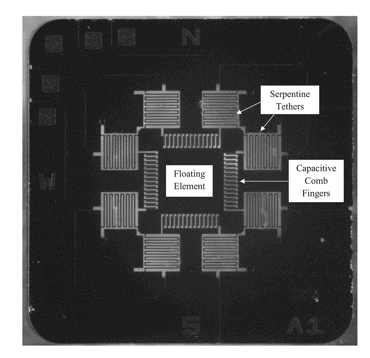
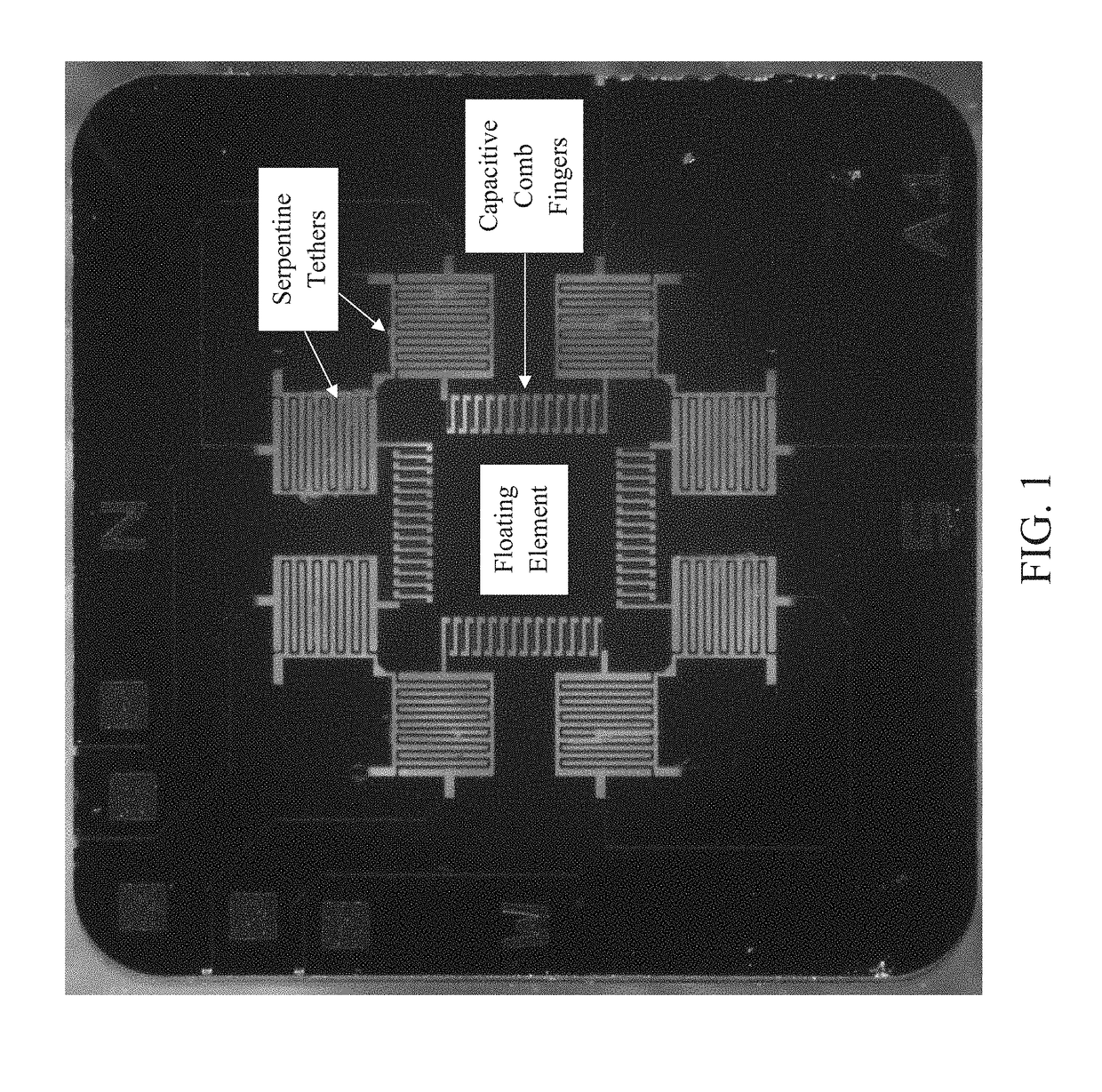
MEMS capacitive wall shear stress vector measurement system
a capacitive wall and shear stress technology, applied in the field of mems capacitive wall shear stress vector measurement system, can solve the problems of reducing the efficiency of vehicles during operation, inability to obtain accurate wall shear stress measurement, and subsequently solving problems
- Summary
- Abstract
- Description
- Claims
- Application Information
AI Technical Summary
Benefits of technology
Problems solved by technology
Method used
Image

Examples
example 1
on of a Wall Shear Stress Sensing Device
[0057]Processing steps involved in fabricating an exemplary embodiment of the sensing device provided herein include photolithography, wet etching, layer deposition (PECVD and sputter), and material removal (DRIE) as detailed in FIGS. 6A-6H. Details of the silicon wafer used to fabricate the device are shown in Table 1 below.
TABLE 1Details of the silicon wafer used to fabricate the sensing device.Size100 mm ± 0.1 mm (diameter), 560 μm ± 11 μm(thickness)Orientation± 0.5 degreeHandle Layer500 μm ± 10 μm thick, boron-doped to aresistivity of Buried Oxide layerApproximately 2 μm ± 5% thickDevice Layer60 μm ± 1 μm thick, phosphorous-doped toa resistivity of Surface OxidesNone specifiedSOI Wafer SourceUltrasil
[0058]Specifically, the fabrication comprises the following steps:
[0059]I. Wafer Treatment[0060]A: Clean wafers (FIG. 6A)[0061]1.) SC1 clean[0062]a.) Etch in 5:1:1 H2O:H2O2:NH4OH for 10 minutes at 75° C.[0063]b.) Triple rinse with DI water[0064...
example 2
nt of Wall Shear Stress Using the Device
[0162]To measure wall shear stress in a static environment (e.g., a laminar flow cell), a mass-flow controller was used to generate a steady pressure gradient over the sensing device which was enclosed in a laminar flow cell. Dynamic response, on the other hand, was characterized using an acoustic plane wave tube (PWT). Utilizing a variable distance sound hard back plate and dual reference microphones, the sensing device was placed at the pressure null of a standing wave pattern, maximizing shear force at that location with a frequency response function generated as a result.
[0163]To ascertain sensitivity to pressure in the out-of-plane direction the sensor was flush-mounted in the sound hard boundary termination. Characterization of up to approximately 6.7 kHz cut-on of higher order modes can be carried out in PWT facilities. Furthermore, the sensing device can be tested at a wide range of temperature (e.g., −70° C. to 180° C.) and humidity (...
example 3
n Using Finite Element Analysis
[0165]As a confirmation of modeling validity, optimized design variables were used to create structures in the COMSOL finite element analysis software. Structural resonant modes were investigated using the eigenfrequency analysis. Results for the design with a 2 mm floating element, N=11 meander count, and 5 kHz resonance target are described herein, as these parameters are employed in the exemplary dual-axis wall stress sensor. A list of resonant frequency values is found in Table 2 below.
TABLE 2Resonant frequencies for analyzed structural modes.ModeFrequencyNumber(Hz)Mode Type14,882Diagonal translation24,882Diagonal translation34,974Transverse48,701Rotational59,339Tilting69,340Tilting737,521Flexing745,269Translational
[0166]The first two resonant modes were of nearly identical frequency along the two diagonal in-plane lines, as seen in FIG. 7 and FIG. 8. The third mode, seen in FIG. 9, was in the out-of-plane direction, with a frequency only slightly ...
PUM
| Property | Measurement | Unit |
|---|---|---|
| dynamic shear stress | aaaaa | aaaaa |
| carrier frequency | aaaaa | aaaaa |
| carrier frequency | aaaaa | aaaaa |
Abstract
Description
Claims
Application Information