Microelectromechanical switch with metamaterial contacts

a micro-electromechanical switch and contact technology, applied in contact devices, waveguide devices, electrical apparatus, etc., can solve the problems of high actuation voltage, high insertion loss, and high actuation voltage of rf mems switches, and achieve the effect of increasing the flexibility of primary deflectable beams and increasing the flexibility of secondary deflectable beams

Active Publication Date: 2018-09-13
SYNERGY MICROWAVE CORP
View PDF0 Cites 7 Cited by
  • Summary
  • Abstract
  • Description
  • Claims
  • Application Information

AI Technical Summary

Benefits of technology

[0014]In some examples, the middle portion of the primary deflectable beam may have a plurality of perforations forming a lattice structure. The perforations may increase the flexibility of primary deflectable beam. Each corner of the middle portion may extend outward toward the first or second end in a serpentine pattern. The extended corners of one side of the middle portion may meet at the first end, while the extended corners of the other side of the middle portion meet at the second end. In this regard, the primary deflectable beam may be less than 150 μm long and yet sufficiently flexible for the middle portion to deflect 1 μm or more downward. The downward deflection may be in response to application of a bias voltage, such as a voltage of about 17 volts or less. Additionally or alternatively, each secondary deflectable beam may include a plurality of perforations forming a lattice structure. The perforations may increase flexibility of secondary deflectable beam.

Problems solved by technology

RF MEMS switches can encounter several drawbacks, including high actuation voltages, high insertion loss, and poor return loss.
These drawbacks are a challenge to designing MEMS switches for operation in the millimeter wave frequency range.
Another problem with RF MEMS switch performance is that it is prone to electromechanical failure after several switching cycles, especially under hot switching conditions.
For instance, the switch may fail due to static friction (or stiction) buildup.
When the moveable part of the switch is pulled into contact with another component of the system (e.g., a signal line), the static friction can cause the switch to become stuck.

Method used


Image

  • Microelectromechanical switch with metamaterial contacts
  • Microelectromechanical switch with metamaterial contacts
  • Microelectromechanical switch with metamaterial contacts

Examples


Embodiment Construction

[0076]The present disclosure provides for RF MEMS switches having improved signal characteristics and reduced vulnerability to stiction.

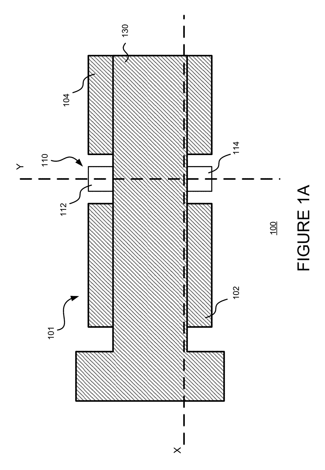
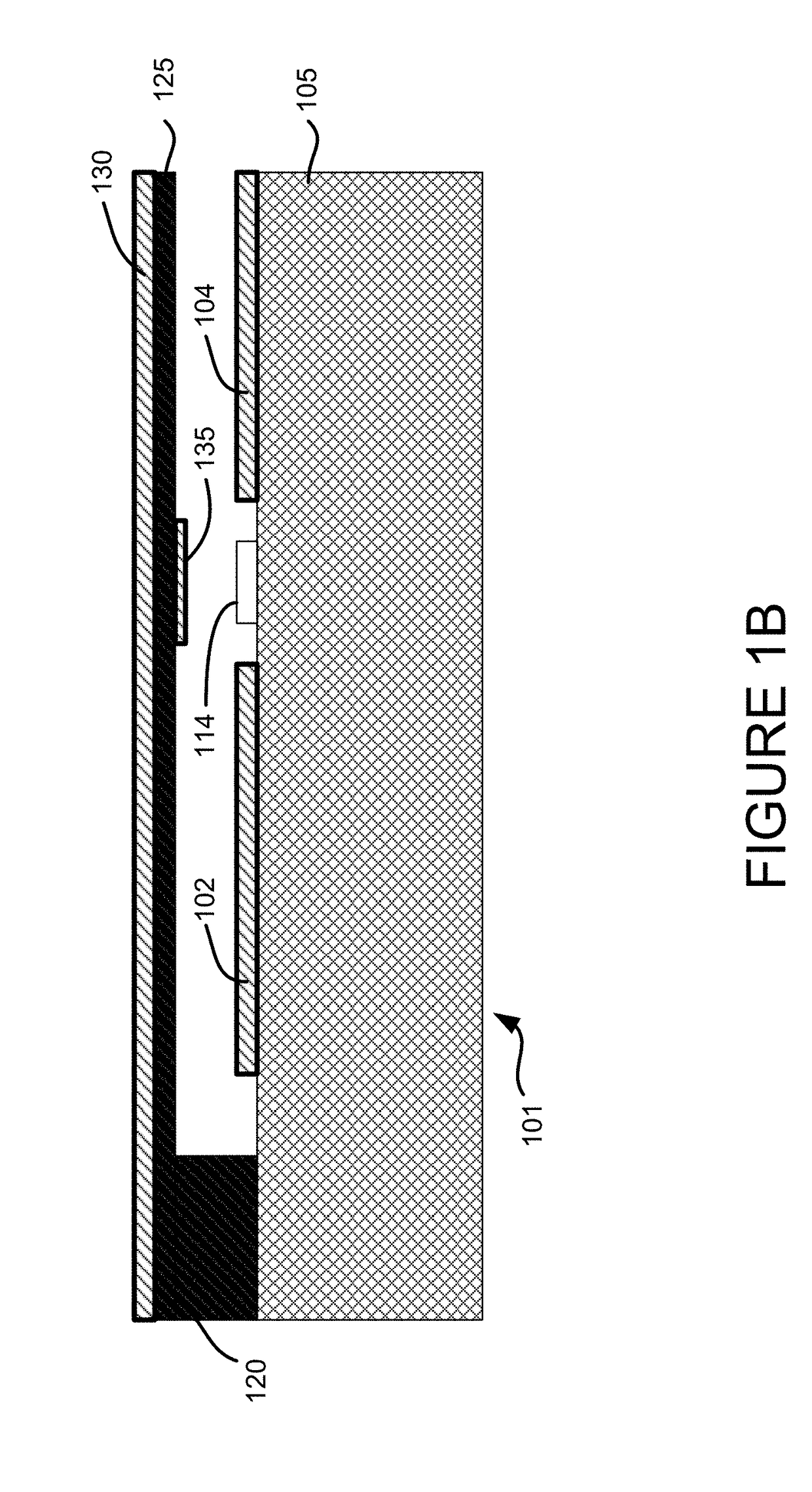
[0077]FIG. 2 shows an RF shunt switch 200 with a doubly-supported cantilever beam 210 formed above a coplanar waveguide formed on a substrate 201. A first end 212 and second end 214 of the beam 210 are supported by respective ground planes 202 and 204 formed in the coplanar waveguide. The middle of the beam 210 is suspended over a signal line 220 formed in the coplanar waveguide. The beam 210 is connected to an actuator (not shown) configured to apply a direct current (DC) bias voltage across the beam 210 the ground planes 202, 204. The DC bias voltage causes the beam 210 to deflect downward.

[0078]In the example of FIG. 2, the signal line 220 includes a conductive layer 222 covered by a thin dielectric layer 224, such as silicon nitride. The dielectric layer may be about 0.2 μm thick. When the beam 210 deflects downward and contacts the signal line ...


PUM


Abstract

A microelectromechanical switch having improved isolation and insertion loss characteristics and reduced liability for stiction. The switch includes a signal line having an input port and an output port between first and second ground planes. The switch also includes a beam for controlling activation of the switch. In some embodiments, the switch further includes one or more defected ground structures formed in the first and second ground planes, and a corresponding secondary deflectable beam positioned over each defected ground structure. In some embodiments, the switch includes a metamaterial structure for generating a repulsive Casimir force.

Description

CROSS-REFERENCE TO RELATED APPLICATIONS[0001]This application claims the benefit of the filing date of U.S. Provisional Patent Application No. 62 / 469,752 filed Mar. 10, 2017, the disclosure of which is hereby incorporated herein by reference.FIELD OF TECHNOLOGY[0002]The present disclosure relates to radio frequency (RF) switches, or more particularly RF micro electromechanical system (MEMS) switches.BACKGROUND OF THE INVENTION[0003]RF MEMS switches have previously been employed in microwave and millimeter-wave communication systems, such as in signal routing for transmit and receive applications, switched-line phase shifters for phased array antennas, and wide-band tuning networks for modern communication systems. MEMS is typically a silicon-based integrated circuit technology with moving mechanical parts that are released by means of etching sacrificial silicon dioxide layers.[0004]FIGS. 1A-1C illustrate an example circuit design of a cantilevered out-of-plane RF MEMS switch 100. F...

Claims


Application Information

Patent Timeline
Patent Type & Authority Applications(United States)
IPC IPC(8): H01H59/00H01H1/00
CPCH01H2059/0027H01H2205/004H01H2239/004H01H2239/018H01H2001/0052H01H2001/0084H01H2001/0089H01H59/0009H01H1/0036H01P1/127H01P1/2005
Inventor KOUL, SHIBAN K.PODDAR, AJAY KUMARROHDE, ULRICH L.
Owner SYNERGY MICROWAVE CORP
Why Eureka
Try Eureka