
Laser marking of raw anode foil to induce uniform pattering and etching with oxide passivation mask

Active Publication Date: 2018-10-04
PACESETTER INC
View PDF9 Cites 2 Cited by
  • Summary
  • Abstract
  • Description
  • Claims
  • Application Information

AI Technical Summary

Benefits of technology

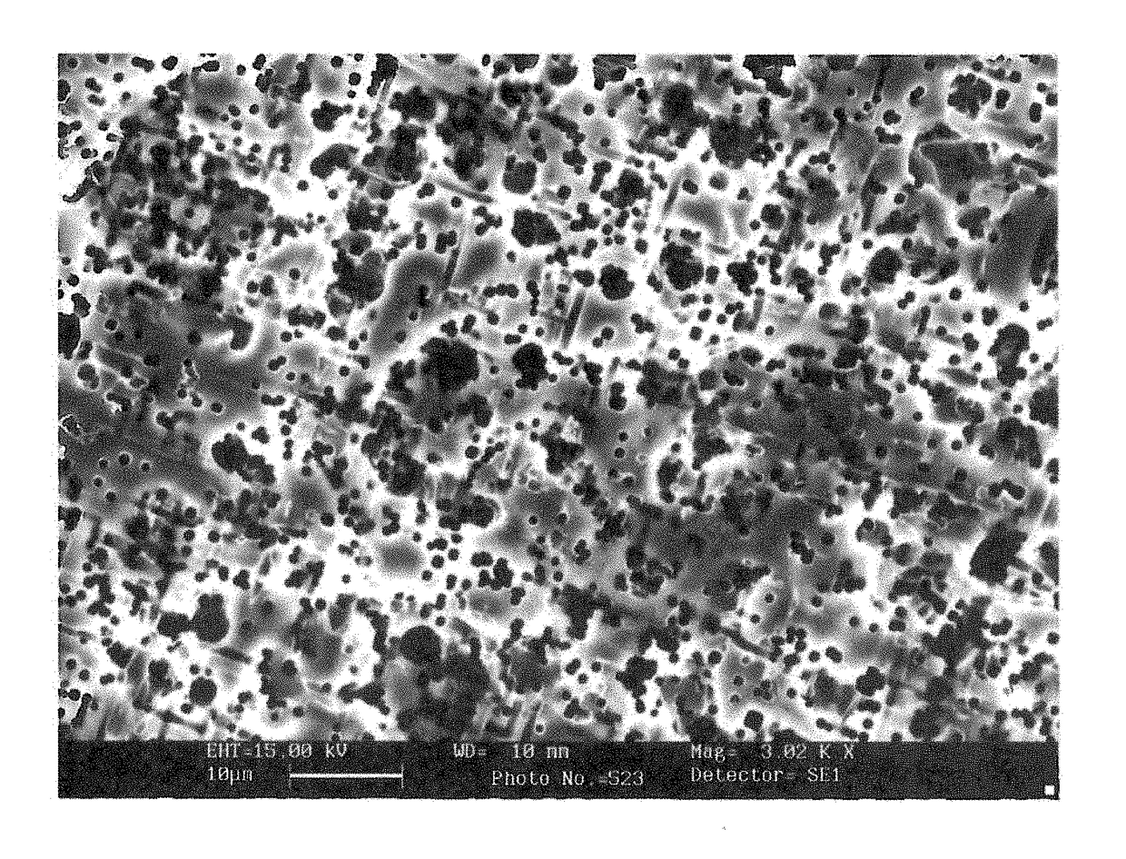
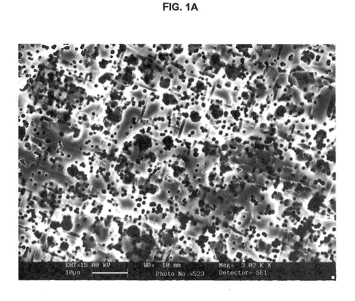
The present invention is a method of making an electrode for a capacitor from a foil. This is achieved by first growing layers of hydrate and oxide on the foil, then using a laser to create small marks on the surface of the foil. This laser marks the areas where the foil will be etched to create a high surface area, which increases the capacitance of the capacitor. The laser uses a femtosecond laser which causes very precise and efficient damage to the oxide layer without causing damage to the underlying aluminum substrate. This method allows for a higher density of capacitors to be produced from the foil.

Problems solved by technology

Since these capacitors must typically store approximately 30-40 joules, their size can be relatively large, and it is difficult to package them in a small implantable device.
A patient who has a device implanted may often be bothered by the presence of the large object in his or her pectoral region.
Furthermore, the generally rectangular shape can in some instances lead to pocket erosion at the somewhat curved corners of the device.
The size and configuration of the capacitors has been a major stumbling block in achieving this goal.

Method used


Image

  • Laser marking of raw anode foil to induce uniform pattering and etching with oxide passivation mask
  • Laser marking of raw anode foil to induce uniform pattering and etching with oxide passivation mask
  • Laser marking of raw anode foil to induce uniform pattering and etching with oxide passivation mask

Examples


Embodiment Construction

[0025]In the detailed description that follows, references to “one embodiment,”“an embodiment,”“an illustrative embodiment,” etc., indicate that the embodiment described may include a particular feature, structure, or characteristic, but every embodiment may not necessarily include the particular feature, structure, or characteristic. Moreover, such phrases are not necessarily referring to the same embodiment. Further, when a particular feature, structure, or characteristic is described in connection with an embodiment, it is submitted that it is within the knowledge of one skilled in the art to affect such feature, structure, or characteristic in connection with other embodiments whether or not explicitly described.

[0026]It should be understood that not all embodiments of the invention include the discussed features, advantages or modes of operation. Alternate embodiments may be devised without departing from the scope of the invention, and well-known elements of the invention may ...


PUM

PropertyMeasurementUnit
Temperatureaaaaaaaaaa
Sizeaaaaaaaaaa
Speedaaaaaaaaaa

Abstract

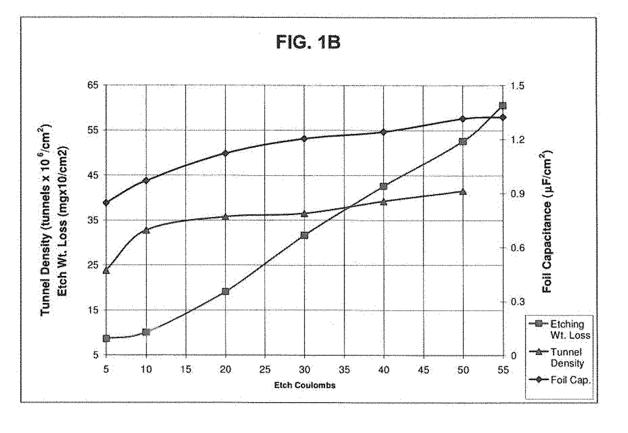
A method of producing an electrode for use in the manufacture of electrolytic capacitors for implantable cardioverter defibrillators comprises first growing a hydrate layer and / or formed oxide layers of the foil, applying a laser beam to portions of the foil to ablate the aluminum oxide foil surface before etching in order to induce etching in the specific areas, and then, etching the foil. The laser marks the oxide layer in a pulsed spot pattern through the hydrate layer and / or formed oxide layer leaving a dimpled nascent aluminum surface. The oxide layer left behind is a mask and the fresh aluminum areas are the high etching activation sites. After marking the aluminum oxide foil surface, the foil may be electrochemically etched in an electrolyte containing chloride and / or various oxidative species.

Description

PRIORITY[0001]The present application relates to and claims priority from U.S. provisional patent application Ser. No. 62 / 481,433, filed Apr. 4, 2017, entitled “LASER MARKING OF RAW ANODE FOIL TO INDUCE UNIFORM PATTERING AND ETCHING WITH OXIDE PASSIVATION MASK,” which is hereby expressly incorporated by reference in their entirety to provide continuity of disclosure.BACKGROUND OF THE INVENTIONField of the Invention[0002]The present invention is directed to a method of producing an electrode for use in the manufacture of electrolytic capacitors and more particularly to a method of creating porous electrode foil for use in multiple electrode stack configuration electrolytic capacitors of the type used in implantable cardioverter defibrillators (ICDs).Related Art[0003]Compact, high voltage capacitors are utilized as energy storage reservoirs in many applications, including implantable medical devices. These capacitors are required to have a high energy density since it is desirable to ...

Claims


Application Information

Patent Timeline
IPC IPC(8): A61N1/05B23K26/00B23K26/082B23K26/073B23K26/362B23K26/0622H01G9/00H01G9/055H01G9/045
CPCA61N1/0563B23K26/082B23K26/073H01G9/045B23K26/359H01G9/0029H01G9/055B23K26/362B23K26/0624A61N1/3956A61N1/3975B23K26/361H01G9/0032
Inventor BOWEN, DAVID R.HEMPHILL, RALPH JASONERICKSON, KURT J.
Owner PACESETTER INC
Learn More