

Organic electroluminescent device
a technology of electroluminescent devices and electroluminescent materials, which is applied in the direction of luminescent compositions, organic chemistry, chemistry apparatus and processes, etc., can solve the problems of deterioration of devices, material degradation, and inability to achieve improvement in luminous efficiency
- Summary
- Abstract
- Description
- Claims
- Application Information
AI Technical Summary
Benefits of technology
Problems solved by technology
Method used
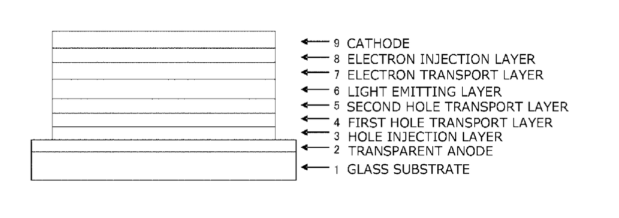
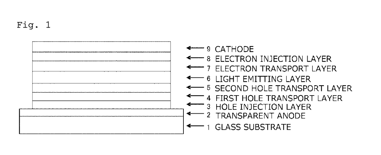
Image

Examples
example 1
Synthesis of bis(biphenyl-4-yl)-(6-phenylbiphenyl-3-yl)amine (Compound 5-2)
[0248]Bis(biphenyl-4-yl)-(6-bromobiphenyl-3-yl)amine (11.8 g), toluene (94 mL), phenylboronic acid (2.7 g), and an aqueous solution obtained by previously dissolving potassium carbonate (5.9 g) in water (36 mL) were added into a nitrogen-substituted reaction vessel and aerated with nitrogen gas under ultrasonic irradiation for 30 minutes. Tetrakistriphenylphosphine palladium (0.74 g) was added thereto, and the resulting mixture was heated and stirred at 72° C. for 18 hours. After the mixture was cooled to a room temperature, an organic layer was collected by liquid separation. The organic layer was washed with water, and washed with a saturated salt solution sequentially, and then dried over anhydrous magnesium sulfate and concentrated to obtain a crude product. Subsequently, the crude product was purified using column chromatography, whereby a white powder of bis(biphenyl-4-yl)-(6-phenylbiphenyl-3-yl)amine (...
example 2
Synthesis of bis(biphenyl-4-yl)-{6-(naphthyl-1-yl)biphenyl-3-yl}amine (Compound 5-3)
[0252]The reaction was carried out under the same conditions as those of Example 1, except that phenylboronic acid was replaced with 1-naphthylboronic acid, whereby a white powder of bis(biphenyl-4-yl)-{6-(naphthyl-1-yl)biphenyl-3-yl}amine (Compound 5-3, 9.2 g, yield: 61%) was obtained.
[0253]The structure of the obtained white powder was identified by NMR.
[0254]1H-NMR (CDCl3) detected 33 hydrogen signals, as follows.
[0255]δ (ppm)=7.84-7.87 (3H), 7.67-83 (6H), 7.26-7.64 (18H) 7.02-7.04 (6H)
example 3
Synthesis of bis(biphenyl-4-yl)-{6-(9,9-dimethylfluoren-2-yl)biphenyl-3-yl}amine (Compound 5-1)
[0256]The reaction was carried out under the same conditions as those of Example 1, except that phenylboronic acid was replaced with (9,9-dimethylfluoren-2-yl)boronic acid, whereby a white powder of bis(biphenyl-4-yl)-{6-(9,9-dimethylfluoren-2-yl)biphenyl-3-yl}amine (Compound 5-1, 9.0 g, yield: 57%) was obtained.
[0257]The structure of the obtained white powder was identified by NMR.
[0258]1H-NMR (CDCl3) detected 39 hydrogen signals, as follows.
[0259]δ (ppm)=7.56-7.64 (10H), 7.26-50 (18H), 7.02-7.16 (5H), 1.26 (6H)
PUM
| Property | Measurement | Unit |
|---|---|---|
| Energy | aaaaa | aaaaa |
| Time | aaaaa | aaaaa |
| Time | aaaaa | aaaaa |
Abstract
Description
Claims
Application Information