Ultrasonic material, method for preparing the material, and ultrasonic probe comprising the material

a technology of ultrasonic transducers and materials, applied in ultrasonic/sonic/infrasonic diagnostics, manufacturing tools, therapy, etc., can solve the problems of poor flexibility, large volume of low-frequency ultrasonic transducers, complex manufacturing process, etc., and achieve accurate diagnosis and treatment. , the effect of small siz

Inactive Publication Date: 2018-12-06
HUAZHONG UNIV OF SCI & TECH
View PDF0 Cites 0 Cited by
  • Summary
  • Abstract
  • Description
  • Claims
  • Application Information

AI Technical Summary

Benefits of technology

[0005]In view of the above-described problems, it is one objective of the invention to provide an ultrasonic material, a method for preparing the same, and an endoscopic photoinduced ultrasonic probe comprising the same. The endoscopic photoinduced ultrasonic probe is small-sized and accurate in diagnosis and treatment, and meanwhile, the diagnosis and treatment can be performed simultaneously.

Problems solved by technology

However, low-frequency ultrasonic transducers are bulky, and inaccurate in their treatment effect.
However, the piezoelectric material for manufacturing the transducers is high in hardness, poor in flexibility, which leads to a complex manufacturing process.

Method used


Image

  • Ultrasonic material, method for preparing the material, and ultrasonic probe comprising the material
  • Ultrasonic material, method for preparing the material, and ultrasonic probe comprising the material
  • Ultrasonic material, method for preparing the material, and ultrasonic probe comprising the material

Examples


example 1

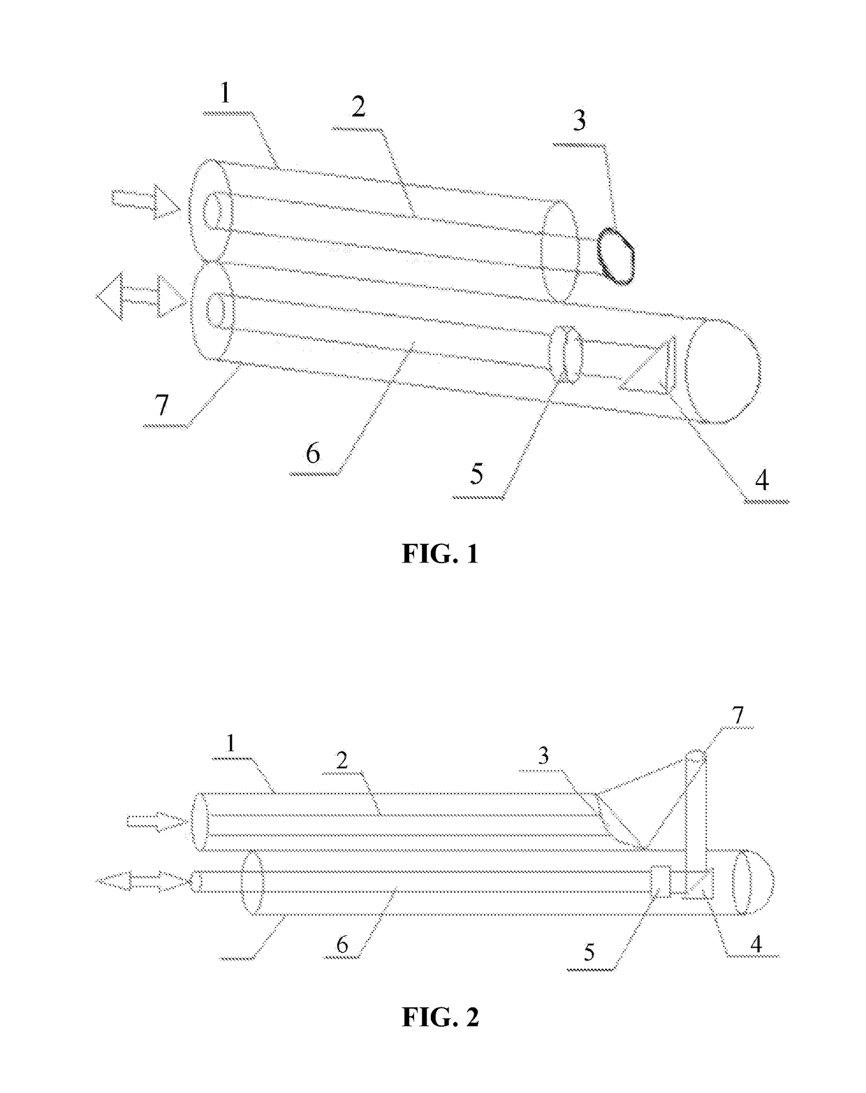
[0041]FIG. 1 is a three-dimensional schematic diagram of an endoscopic photoinduced ultrasonic probe. FIG. 2 is a cross-sectional view of the endoscopic photoinduced ultrasonic probe. A second incident optical fiber 6 is bonded with the cylindrical photoinduced ultrasonic material 5. A diameter of the cylindrical photoinduced ultrasonic material 5 is 2 mm A center of the second incident optical fiber 6 and a center of the cylindrical photoinduced ultrasonic material 5 are on the same line. A first incident optical fiber 2 is bonded with the focused light-induced ultrasonic material 3. A diameter of the focused light-induced ultrasonic material 3 is 2 mm. The first incident optical fiber is seamlessly connected to the focused light-induced ultrasonic material. A total reflector 4 is fixed at one side of the cylindrical photoinduced ultrasonic material 5 and is 1 mm away from the cylindrical photoinduced ultrasonic material. An axis of the total reflector 4 and a center of the cylindr...

example 2

[0043]FIG. 1 is a three-dimensional schematic diagram of an endoscopic photoinduced ultrasonic probe. FIG. 2 is a cross-sectional view of the endoscopic photoinduced ultrasonic probe. A second incident optical fiber 6 is bonded with the cylindrical photoinduced ultrasonic material 5. A diameter of the cylindrical photoinduced ultrasonic material 5 is 3 mm A center of the second incident optical fiber 6 and a center of the cylindrical photoinduced ultrasonic material 5 are on the same line. A first incident optical fiber 2 is bonded with the focused light-induced ultrasonic material 3. A diameter of the focused light-induced ultrasonic material 3 is 5 mm. The first incident optical fiber is seamlessly connected to the focused light-induced ultrasonic material. A total reflector 4 is fixed at one side of the cylindrical photoinduced ultrasonic material 5 and is 1 mm away from the cylindrical photoinduced ultrasonic material. An axis of the total reflector 4 and a center of the cylindr...

example 3

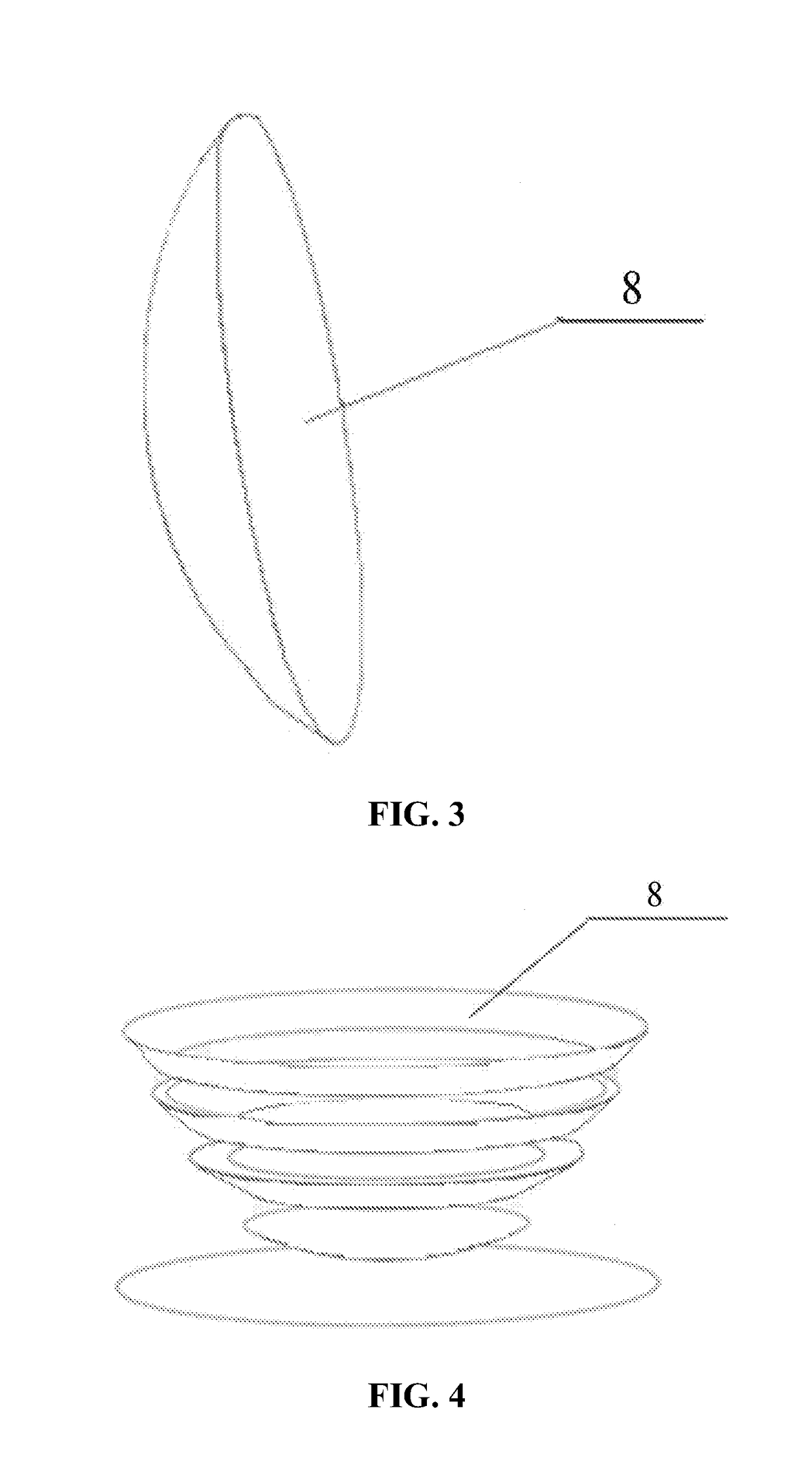
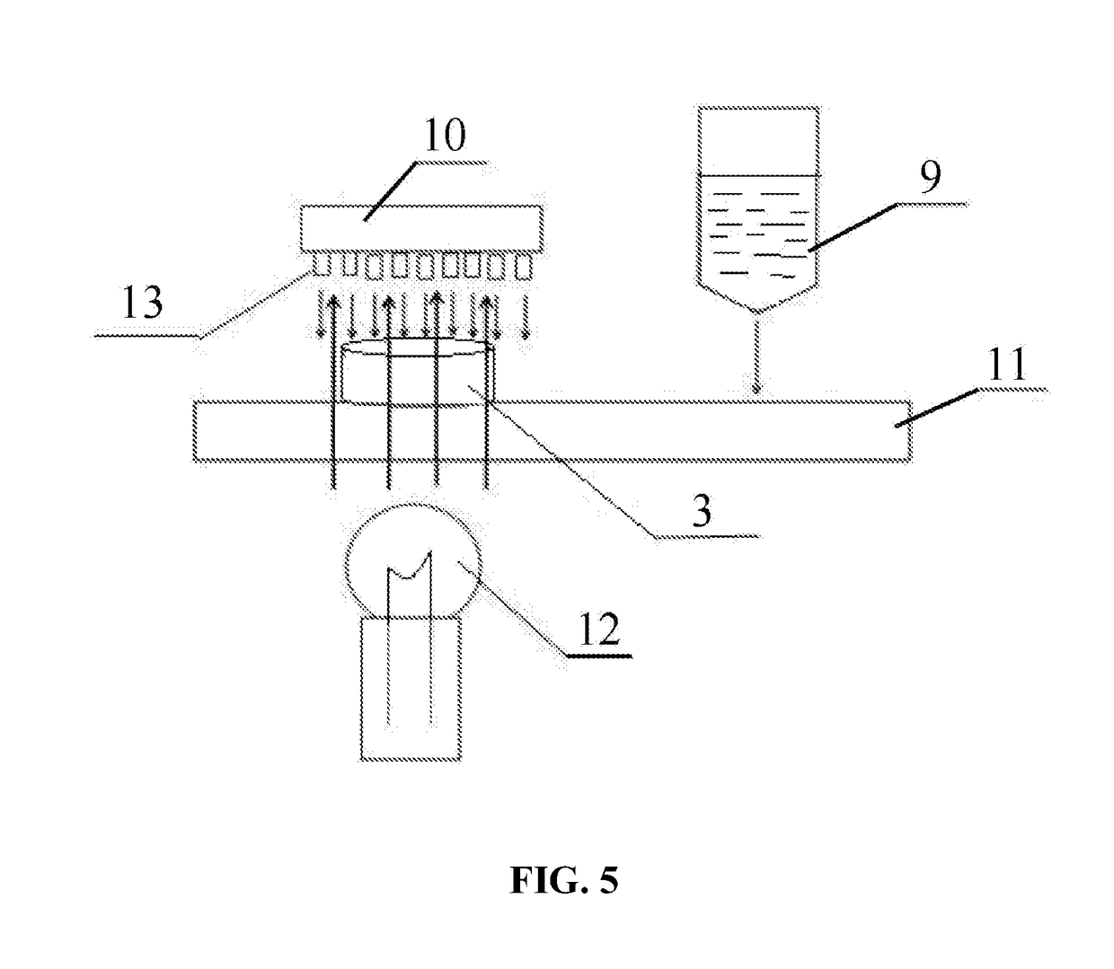
[0045]FIG. 3 is a three-dimensional schematic diagram of a focused light-induced ultrasonic material 3, and FIG. 4 is a diagram showing a production process of the focused light-induced ultrasonic material 3. FIG. 5 is a schematic diagram of a mask image projection based stereo lithography apparatus. The focused light-induced ultrasonic material 3 is prepared by two steps: 1) methyl ethyl ketone was mixed with ethyl alcohol to form azeotropic mixture. Carbon nanotube powders and dispersant in the azeotropic mixture were ground using stainless steel grinding balls of a planetary ball mill for 10 hrs at a speed of 150 rpm to yield a dispersoid. The dispersoid was dried for 11 hrs at 40° C. Dry carbon nanotube powders were yielded when solvent in the dispersoid was evaporated. 2) The dry carbon nanotube powders in 1) were mixed with the light-cured resin SI500 by ball milling for 1 hr to form a sizing mixture, and a weight ratio of the dry carbon nanotube powders to the light-cured res...


PUM

PropertyMeasurementUnit
temperatureaaaaaaaaaa
thickaaaaaaaaaa

Abstract

A method for preparing an ultrasonic material, including: 1) mixing methyl ethyl ketone with ethyl alcohol to prepare an azeotropic mixture; uniformly mixing carbon nanotube powders with a dispersant in the azeotropic mixture to yield a dispersoid; drying the dispersoid to yield dry carbon nanotube powders; 2) mixing the dry carbon nanotube powders in 1) with a light-cured resin to form a sizing mixture; 3) evenly distributing the sizing mixture in 2) over a plane of a mask image projection based stereo lithography apparatus to form a sizing mixture layer; 4) switching a design model of focused light-induced ultrasonic material to a two-dimensional image; projecting the two-dimensional image on a surface of the sizing mixture layer in 3); 5) exposing the sizing mixture layer in 3) under visible light and solidifying the sizing mixture layer; and 6) repeating 3)-5) to complete printing of the ultrasonic material.

Description

CROSS-REFERENCE TO RELATED APPLICATIONS[0001]Pursuant to 35 U.S.C. § 119 and the Paris Convention Treaty, this application claims foreign priority to Chinese Patent Application No. 201710417275.9 filed Jun. 6, 2017, the contents of which are incorporated herein by reference. Inquiries from the public to applicants or assignees concerning this document or the related applications should be directed to: Matthias Scholl P.C., Attn.: Dr. Matthias Scholl Esq., 245 First Street, 18th Floor, and Cambridge, Mass. 02142.BACKGROUND OF THE INVENTIONField of the Invention[0002]The invention relates to an ultrasonic material, a method for preparing the material, and an endoscopic photoinduced ultrasonic probe comprising the same.Description of the Related Art[0003]Conventionally, the piezoelectric ultrasonic transducer is used to diagnose and treat blood vessel pathologies. However, low-frequency ultrasonic transducers are bulky, and inaccurate in their treatment effect.[0004]In recent years, hi...

Claims


Application Information

Patent Timeline
Patent Type & Authority Applications(United States)
IPC IPC(8): A61N7/00B29C64/314B29C64/135A61B8/00
CPCA61N7/00B29C64/314B29C64/135A61B8/42B33Y40/00A61N2007/0043A61N2007/0004A61N2007/0056A61N2007/0052A61B8/4444B33Y80/00A61N7/02A61N7/022A61B2017/00526A61N2007/0065
Inventor ZHU, BENPENGSHEN, MINGKEYANG, XIAOFEIZHANG, YUEOUYANG, JUN
Owner HUAZHONG UNIV OF SCI & TECH
Why Eureka
Try Eureka