Radar level gauge

Inactive Publication Date: 2018-12-06
ROSEMOUNT TANK RADAR
View PDF1 Cites 3 Cited by
  • Summary
  • Abstract
  • Description
  • Claims
  • Application Information

AI Technical Summary

Benefits of technology

[0027]The transceiver circuitry and processing circuitry may be implemented as separate chips on a common board. However, in order to reduce size and improve environmental impact, it is generally desirable to integrate the transceiver circuitry and processing circuitry in a single integrated circuit (IC), either as a monolithic IC or a

Problems solved by technology

It is noted that mass produced radar systems, e.g. for the automotive industry, is not a new concept.
However, previously available systems have operated in other frequency ranges, e.g. in the 24 GHz area, where only a limited bandwidth is publicly available, i.e. allowable from a regulatory perspective.
Therefore, such previously available radar systems, although similarly beneficial from a cost perspective, have had insufficient band width for high performance radar level gauging.
However, the requirements of a RLG radar system are significantly different from those of an automotive system.
While a radar system in a car typically has more or less unlimited power from a 12 V source, many radar level gauges are powered by en

Method used


Image

  • Radar level gauge
  • Radar level gauge
  • Radar level gauge

Examples


Embodiment Construction

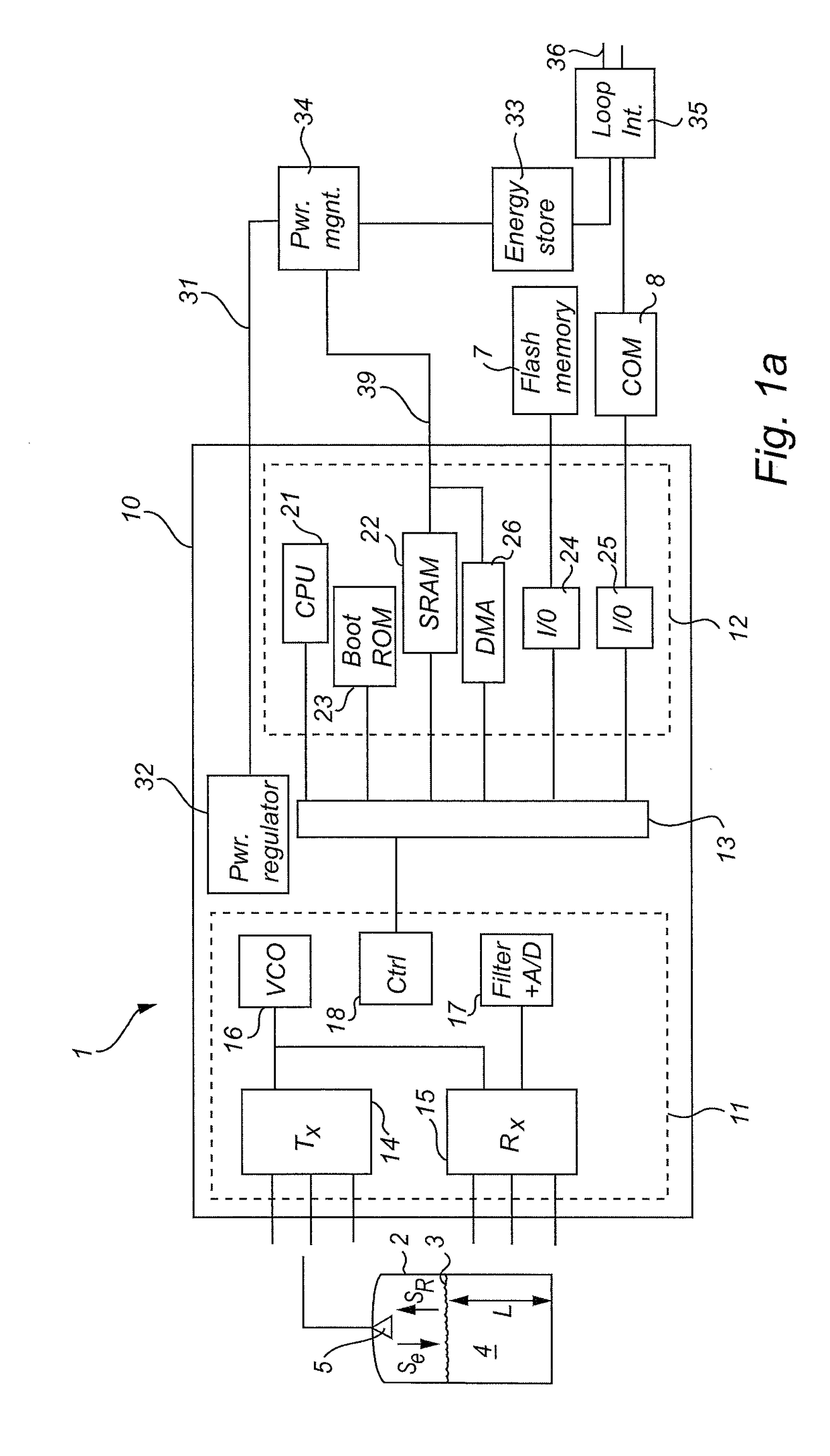
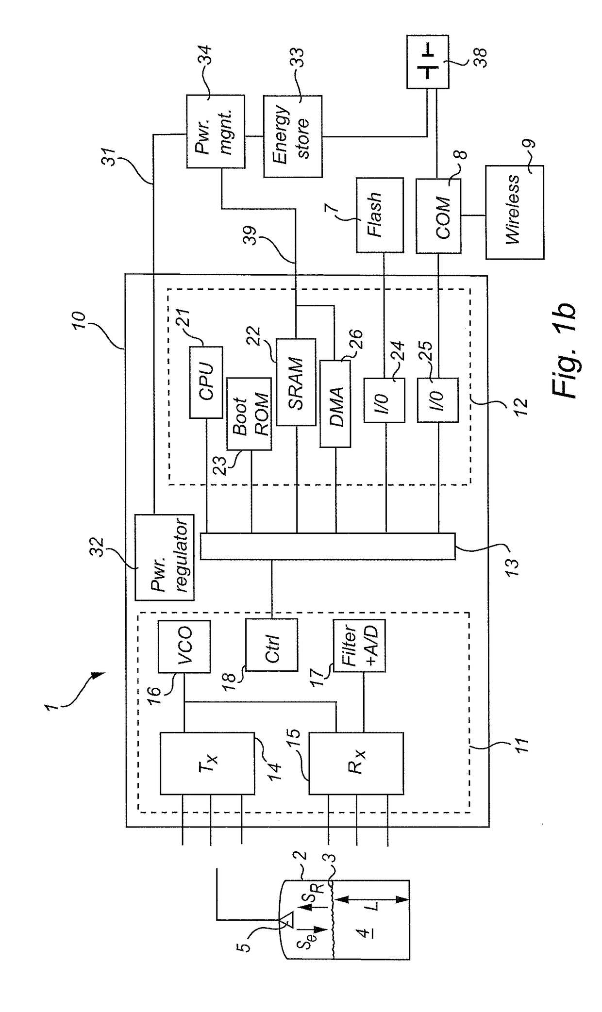
[0034]FIGS. 1a and 1b show very schematically a radar level gauge (RLG) 1 which can be mounted on the roof of a tank 2 in order to measure a distance to a surface 3 of a product 4 kept in the tank. The distance can be used to determine a process variable, such as the filling level L of the tank.

[0035]The RLG 1 has a signal propagation device, here a directional antenna 5, arranged to emit a transmit signal ST into the tank 2 and to receive a reflected signal SR from the tank. The antenna 5 is connected to a radar unit 10, including transceiver circuitry 11 and processing circuitry 12. Further details of the radar unit 10 will be further discussed below. The radar unit 10 is connected to a non-volatile memory, such as a flash memory, 7, and to communication circuitry 8.

[0036]In order to communicate the detected process variable outside the RLG 1, the communication circuitry 8 may be connected to a two-wire control loop 37, typically a two-wire 4-20 mA control loop, via a two-wire int...


PUM


Abstract

A radar level gauge for determining a filling level of a product in a tank, comprising a volatile high-speed working memory, a first processing unit connected to the volatile high-speed working memory, the first processing unit having an active mode in which the first processing unit is turned on and accesses the working memory, and an inactive mode where the first processing unit is turned off, memory loading circuitry, separate from the processor, configured to transfer software code from a non-volatile memory into the volatile high-speed working memory while the processor is in inactive mode, and an auxiliary power connection configured to provide power only to the volatile high-speed working memory and the memory loading circuitry.
With this design, the memory loading circuitry and working memory can be powered separately, thereby allowing loading of software code from the non-volatile memory into the volatile high-speed working memory without activating the relatively power-hungry processor.

Description

FIELD OF THE INVENTION[0001]The present invention relates to a radar level gauge (RLG).BACKGROUND OF THE INVENTION[0002]A recent generation of automotive radar systems include a 77 GHz radar transceiver in combination with suitable processing circuitry. Such systems are adapted to receive power from a 12 V battery supply, and to have a relatively high measurement update rates, e.g. in the order of 10 or even 100 measurements per second. In order to obtain sufficiently fast processing, software code as well as data is stored in a fast (but volatile) memory, such as SRAM. The software code is loaded from a non-volatile memory (e.g. a flash memory) into the SRAM using a boot-loader executed by the processor at each start-up of the system. A typical start-up time is around one second.[0003]Such radar systems typically have a relatively broad bandwidth, e.g. at least one GHz. This makes them potentially useful in the technical field of in radar level gauging in tanks or other containers,...

Claims


Application Information

Patent Timeline
IPC IPC(8): G01F23/28G01S7/40
CPCG01S7/4004G01F23/282G01F23/284G01S13/88G11C5/148G11C11/417G01S13/931G11C11/005G06F13/28
Inventor KLEMAN, MIKAEL
Owner ROSEMOUNT TANK RADAR
Why Eureka
Try Eureka