System, Network, Device and Stacked Spectrum Method for Implementing Spectrum Sharing of Multiple Contiguous and Non-Contiguous Spectrum Bands Utilizing Universal Wireless Access Gateways to Enable Dynamic Security and Bandwidth Policy Management

a technology of stacked spectrum and network infrastructure, applied in data switching networks, instruments, data switching details, etc., can solve the problems of reducing the ability of channels to operate, reducing the effectiveness of some of the fcc's spectrum sharing proposals, and difficulty in re-allocating these bands for new wireless communications services and applications. , to achieve the effect of enhancing security

Inactive Publication Date: 2018-12-27
INCNETWORKS
View PDF0 Cites 43 Cited by
  • Summary
  • Abstract
  • Description
  • Claims
  • Application Information

AI Technical Summary

Benefits of technology

[0053]In embodiments, one or more processors can be configured to: create a virtual radio channel universal wireless access gateway system by; identifying all available spectrum bands usable within a small cell environment or a large cell environment; and combining all available spectrum bands for use in the small cell environment or the large cell environment to improve at least one of quality of service, security capabilities, and transmission throughput for at least one or more wireless devices for use in the digital wireless communication system.
[0065]In embodiments, one or more processors can be configured to insert a security token into a packet payload of at least one IP packet stream for enhancing security.

Problems solved by technology

However, these bands are frequently configured into separated frequency channels, mostly non-contiguously, and utilize different common air interfaces and radio channel protocols, which makes it difficult to re-allocate these bands for new wireless communications services and applications.
However, many within the wireless communication industry has raised concerns and / or skepticism regarding the effectiveness of some of the FCC's spectrum sharing proposals.
Although, this approach has achieved some success, it has two important drawbacks: it eliminates the ability of the channels to operate independently as before, and it requires the adherence to a new standard radio channel format.
Moreover, this approach cannot be used in situations where the channels are separated (not adjacent) or use different common air interfaces and radio channel protocols.
Given the growing demand for more in-building wireless communications services and applications, from the building owner's perspective, the most challenging issue facing the wireless communications industry is improving the quality of service for wireless communications within office buildings.
However, in contrast to the building owner's perspective, the most challenging issue from the building tenant's perspective restricting the radio channel transmission throughput within buildings is the quality of the radio signal transmission within the building.
This radio transmission quality issues result from radio signal loss due to building structures and materials that restrict the radio signals that are being transmitted from “large cell” cellular base station tower systems outdoor as illustrated in a conventional outdoor “large cell” base station tower system 100 in FIG. 1.
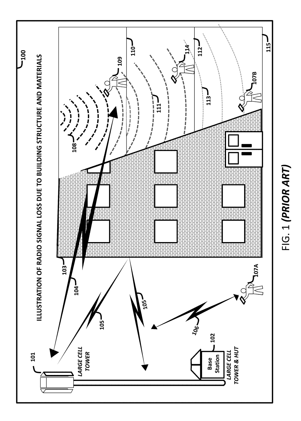
However, due to the building structure 103 as well as the type of materials used within the building, the radio signal power level 111, 113 within the core of the building 103, can be very poor, which can significantly reduce the end-point device 107B, 114 transmission throughputs.
Although, these radio transmission quality issues, which results from radio signal loss due to building structures and materials are well known within the cellular industry, the cellular industry continues to struggle to find an optimum solution for in-building services quality issues.
This situation of signal degradation or loss has caused building owners to demand that the cellular industry address the issue of cellular phone service quality within their buildings.
These requests from cellular end-users are due to the fact that thousands of buildings suffer from poor or weak cellular phone reception and signal coverage within the core structure of the building, resulting in poor cellular phone service quality and transmission throughput within the core structure of many buildings.
However, if the user does not have a direct “line of sight” to the cell tower 201, the cellular signals can be blocked, or the radio signal strength is decreased by certain obstructions, such as, the terrain, building structures and materials.
Even with the installation of a DAS, most cellphone services are challenged indoors and struggle from a “Quality of Service” and / or a data transmission throughput perspective; due to the lack of uniform signal strength based on the design of the DAS configuration 204.
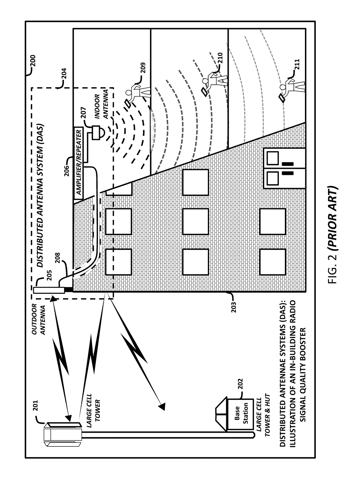
These radio signal fluctuations are due to the variability of the additional layers of building materials that could also block or inhibit cellphone radio signal transmission within the building, if the DAS design is not optimally engineered for the building.
This is a common problem, if the DAS configuration 204 has not been custom designed for the specific building structure, building layout, and materials.
This non-uniform signal strength will also cause an in increase in data error rates, which results in reductions in data transmission throughput at each end-point device 209, 210, and 211 depending on the location of each end-point device with respect to the location of the DAS indoor antenna 207, within the building.
These non-uniform signal strength and radio coverage challenges are the significant quality of services issue for DAS configuration 204 users.
An additional engineering challenge for DAS is the management of radio signals near the windows, if a building 203 has a large number of windows; which means that the cellphone signal may not be completely blocked by building materials unless the windows have radio reflective material covering the windows.
If the windows have radio reflective material covering the windows, then, the end-user's cellphone just experiences a reduction of usable transmission signal near the window.
Although, some DAS configuration may have unique engineering challenges near windows, they can also have special engineering design challenges in the “core” of the building, away from windows, such as, elevator shafts, where the radio signal quality may also be non-uniform; if the DAS configuration is not properly engineered for the internal building 203 structure and materials.
Another drawback of typical conventional DAS configurations is that they are static, and as such, they are not easily changed as the environment within the building changes, without significant cost.
They also do not provide the flexibility to dynamically learn and adapt to meet the changing tenant office space needs, which often involves internal building modifications and reconfigurations to meet new building layout requirements, such as, office space rearrangements.
For instance, when a company's size or spacing needs change, the configuration of the walls may also need to be rearranged, which affects the radio signal propagation environment.
Unless the DAS is also manually reconfigured in accordance with the new office space rearrangement, this new rearrangement of the office space can adversely affect the radio signal level detected by the end-point devices within the building, because the DAS has not been re-engineered to meet the new building configuration requirements.
The inability of the typical conventional DAS configuration to dynamically reconfigure itself through the use of machine-learning techniques to accommodate internal building modifications and external RF frequency modifications increases the infrastructure, installation, and maintenance cost of DAS configurations.
Thus, installation and deployment of a DAS configurations within an owner's building can be cost-prohibitive for the building owner, because the building owner cannot recover these costs.
However, this radio signal rebroadcasting process may not necessarily improve the radio transmission throughput capacity for the many cellular devices operating within the building. FIG. 2 is only an example of one typical type of DAS 204 configuration that has been used to address the inbuilding radio signal coverage quality of services issue.
Because distributed antenna systems operate within RF licensed spectrum bands owned by wireless carriers, an enterprise building owner cannot undertake a DAS deployment within their buildings without involving at least one of the national cellular carriers.
This has been a major point of conflict between building owners and national carriers within the cellular industry.
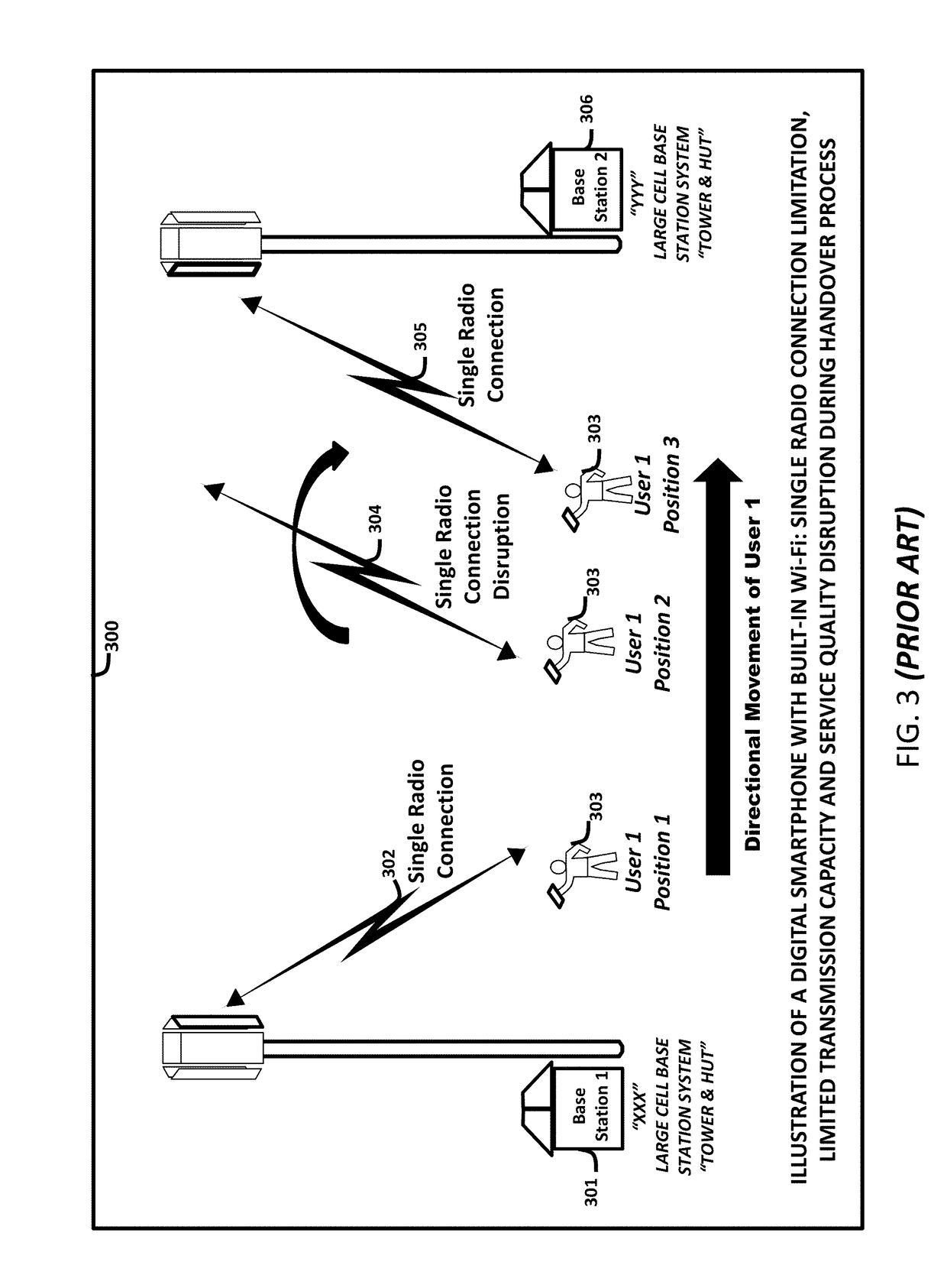
However, additional quality of services issues can remain within the building, such as, service disruption during “handover” and transmission throughput performance issues within the building during high usage periods when many users are occupying the building.
The quality of services issue related to service disruption during “handover” is due to the design limitation of existing cellular smartphone, which can only support a single independent radio transmission connection to a single base station system at a given point in time within the physical radio frequency domain.
Thus, an indoor DAS configuration experiences the same problems during a “handover” process that an end-point device user experiences, when the user is outdoors travelling from one cellular coverage area to another cellular coverage area, which is the transferring of a calling session in progress being transferred from one cellular base station to another cellular base station.
This radio transmission “handover” process is where the service disruption can occur.
Although this arrangement is straightforward, it limits the ability to aggregate more bandwidth for a given end-point device, as well as restricting the distribution of the user's information content over multiple radio resources or radio channels, if they are available to the end-point device.
In addition, this switching operation also interrupts the communication session, while the “handovers” (channel switches) are being negotiated.
Further, even with physical radio frequency channel aggregation, disparate wireless networks and devices cannot utilize multiple physical radio frequency channels simultaneously to effectively increase transmission throughput capacity and enhance security for the wireless end-point devices.

Method used


Image

  • System, Network, Device and Stacked Spectrum Method for Implementing Spectrum Sharing of Multiple Contiguous and Non-Contiguous Spectrum Bands Utilizing Universal Wireless Access Gateways to Enable Dynamic Security and Bandwidth Policy Management
  • System, Network, Device and Stacked Spectrum Method for Implementing Spectrum Sharing of Multiple Contiguous and Non-Contiguous Spectrum Bands Utilizing Universal Wireless Access Gateways to Enable Dynamic Security and Bandwidth Policy Management
  • System, Network, Device and Stacked Spectrum Method for Implementing Spectrum Sharing of Multiple Contiguous and Non-Contiguous Spectrum Bands Utilizing Universal Wireless Access Gateways to Enable Dynamic Security and Bandwidth Policy Management

Examples


example u

-Wag “Small Cell” In-Building Universal Wireless Service Node

[0200]FIG. 11 depicts a Multi-Service Stacked-Spectrum Universal Wireless Access Gateway (U-WAG) Node Functional Block Diagram 1100. The Multi-Service Stacked-Spectrum Universal Wireless Access Gateway (U-WAG) Node 1100 can consist, for example, of four functional subsystems, which communicate with each other through a High-Speed Data Bus 1102. The four exemplary functional subsystems depicted in FIG. 11 include the U-WAG Node Controller and Client Device Emulation Subsystem 1101, the High-Speed Communication and Security Management Subsystem 1104; the Spectrum Identification, Sharing, Management Subsystem 1105, and the Multi-Spectrum Band Radio Subsystem 1103.

[0201]The U-WAG Node Controller and Client Device Emulation Subsystem 1101 serve as the master controller for the U-WAG and manages all communication interaction to the other subsystems 1103, 1104, and 1105 through the High-Speed Data Bus 1102. The High-Speed Communi...


PUM


Abstract

A system and method in various embodiments implements a virtual spectrum band stacking technique facilitating spectrum sharing by converting and combining spectrum bands consisting of several different RF channels, common air interfaces, and radio channel protocols in the radio frequency channel domain to form IP Virtual Radio Channels (IP-VRCs) in the packet data domain. This virtual spectrum stacking technique combines the transmissions of contiguous and non-contiguous RF channels with differing physical layers into IP-VRCs. This technique enables simultaneous parallel high-speed wireless transmission; virtual radio channel hopping for enhanced security; and customized security schemes for different IP-VRC Groups. The deployment of the combination of IP-VRC Groups; Universal “Small Cell” Base Stations; and Universal Wireless End-Point Devices allows the aggregation of all available spectrum bands for use within a building environment. Some benefits of this deployment include expansion of spectrum utilization, service quality, security, applications and transmission throughput for wireless end-point devices.

Description

CROSS-REFERENCE TO RELATED APPLICATIONS[0001]This application is a Continuation of U.S. patent application Ser. No. 15 / 846,188, filed Dec. 18, 2017, now pending, which is a Continuation-In-Part of U.S. patent application Ser. No. 15 / 284,427, filed on Oct. 3, 2016, now pending, which claims benefit to U.S. Provisional Patent Application No. 62 / 235,865, filed on Oct. 1, 2015, now expired. This application is a Continuation-In-Part of U.S. patent application Ser. No. 15 / 151,405, filed on May 10, 2016, now pending, which is a Divisional of U.S. patent application Ser. No. 13 / 727,511, filed on Dec. 26, 2012, now U.S. Pat. No. 9,338,054, issued on May 10, 2016, which is a Continuation of U.S. patent application Ser. No. 13 / 710,339, filed on Dec. 10, 2012, now abandoned, which is a Divisional of U.S. patent application Ser. No. 12 / 752,087, filed on Mar. 31, 2010, now U.S. Pat. No. 8,332,517, issued on Dec. 11, 2012 all of which are hereby incorporated by reference.BACKGROUND OF THE INVENTI...

Claims


Application Information

Patent Timeline
Patent Type & Authority Applications(United States)
IPC IPC(8): H04M15/00H04W64/00H04W4/50H04W36/14H04W4/14H04M7/00H04W36/32H04L29/08H04L12/24H04L12/64H04L12/14G06Q50/18G06Q30/06
CPCH04L12/14H04M7/0063H04L41/5067H04L67/306H04L41/0803H04L12/6418H04W36/32H04W36/14H04M15/8083H04W64/00H04L2012/6421H04L67/1068H04L41/5019H04M15/8016H04W4/50G06Q30/0631G06Q50/188H04W4/14H04L41/5029H04L69/16H04L67/04H04L67/142H04W16/14H04W36/0011H04W4/33H04W88/06H04W48/20H04W84/045H04W88/085H04W24/02H04L67/565H04L67/56H04L41/0895H04L41/0893
Inventor RUSSELL, JESSE E.MILLER, II, ROBERT R.
Owner INCNETWORKS
Why Eureka
Try Eureka