Three-dimensional printer

a three-dimensional printer and printer body technology, applied in the field of three-dimensional printing, can solve the problems of increasing assembly costs and time, reducing the efficiency of printing and assembly, and reducing the complexity of printer assembly, so as to achieve the effect of improving assembly, adding additional printing and machining costs, and being easy to remov

Active Publication Date: 2019-01-31
NORTHWORKS AUTOMATION INC
View PDF3 Cites 6 Cited by
  • Summary
  • Abstract
  • Description
  • Claims
  • Application Information

AI Technical Summary

Benefits of technology

[0010]One proposed solution is coating a filament with nanoparticles, and exposing the print to microwave radiation. While an effective technique, this adds additional printing and machining costs, and can be a difficult technique for accurate control. Another proposed solution is applying glue or solvent between layers, but this solution also requires expensive hardware to implement. Thus, there is a need for techniques for vertical strengthening of 3D printed objects.
[0011]An improved 3D printer includes a print bed having vacuum means for securing the print object to the bed. The vacuum provides airflow through holes in the print bed, securing the print object or a ba

Problems solved by technology

But with these developments, deficiencies still exist in the design of 3D printer systems, as well as 3D printing techniques.
For example, 3D printer assembly and printhead movements cause vibrations.
In current designs, as the amount of bracing increases, so does the complexity of printer assembly.
This complexity typically includes more cross bracing members, increasing assembly costs and time.
The increased complexity also complicates varying the size of the 3D printer itself, where a larger print bed and larger printhead movement area requires more bracing.
Currently, many 3D printer assemblies are built using modular techniques failing to provide required long term stability and rigidity.
Also, these current techniques are inadequate for bracing and stability, because of the high degree of movement and direction change of the 3D printhead.
Another complication with 3D printers is removing the printed object.
Once the print job is complete, problems arise with a print object sticking to the print bed.
Other techniques include using a magnetic print bed and a print base having

Method used


Image

  • Three-dimensional printer
  • Three-dimensional printer
  • Three-dimensional printer

Examples


Embodiment Construction

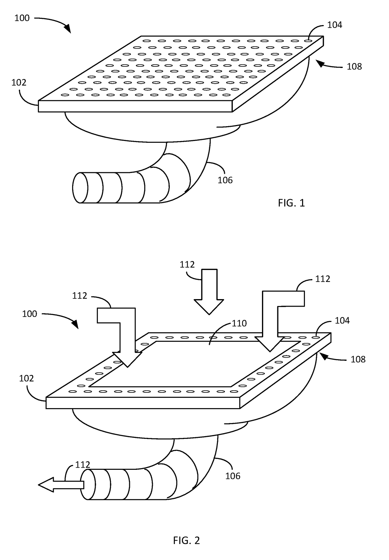
[0033]FIG. 1 illustrates a perspective view of a print bed 100 providing for improved 3D printing. The print bed 100 includes a top layer 102 having a plurality of air holes 104 therein. A vacuum hose 106 is connected to a bottom layer 108.

[0034]The print bed 100 may be composed of any suitable material, such as but not limited to metal or plastic. The bed 100 allows for airflow through the holes 104. Varying embodiments allow for different sizing and placement of air holes, including one embodiment may include pin-prick size air holes, whereas other embodiments may include larger holes. The specific sizing of the air hole 104 is not limiting, such that the air hole 104 in combination with the air hose 106 provides for air flow therethrough.

[0035]While not directly illustrated, the air hose 106 connects to a vacuum or other type of air suction device. The vacuum may be any suitable type of device operative to pull air in through the air holes 104 and down the tube 106. In varying em...


PUM

PropertyMeasurementUnit
Heataaaaaaaaaa
Stabilityaaaaaaaaaa

Abstract

An improved 3D printer includes an airflow enabled print bed ensuring secure placement of a print base prior to printing. The modular assembly technique provides for improved ease of manufacture and assembly, as well as adjustments of print sizing. The improved printhead includes a heat sink disposed internally therein for improved heat and cooling properties. The printhead itself includes z-axis position detection techniques. The inclusion of VSU insertion techniques in software modeling and printing further improves the print operations by including vertical stability for the print object.

Description

RELATED APPLICATIONS[0001]The present application is a continuation-in-part of and claims priority to U.S. patent application Ser. No. 15 / 659,433, filed Jul. 25, 2017, entitled “PRINTER HEAD Z-AXIS ALIGNMENT SYSTEM AND METHOD,” the entirety of which is hereby incorporated by reference.COPYRIGHT NOTICE[0002]A portion of the disclosure of this patent document contains material, which is subject to copyright protection. The copyright owner has no objection to the facsimile reproduction by anyone of the patent document or the patent disclosure, as it appears in the Patent and Trademark Office patent files or records, but otherwise reserves all copyright rights whatsoever.FIELD OF INVENTION[0003]The disclosed technology relates generally to three-dimensional printing and more specifically to improvements with a three-dimensional printing system and method.BACKGROUND[0004]Well known developments exist in three-dimensional (3D) printing technology. But with these developments, deficiencies...

Claims


Application Information

Patent Timeline
IPC IPC(8): B29C64/245B29C64/393B33Y50/02B33Y30/00B29C64/379B29C64/209B33Y40/00
CPCB29C64/245B29C64/393B33Y50/02B33Y30/00B29C64/379B29C64/209B33Y40/00B29C64/232B29C64/386B33Y50/00B29C64/112B29C64/106B29C64/20
Inventor CISCON, LAWRENCEWISE, JAMES D.
Owner NORTHWORKS AUTOMATION INC
Why Eureka
Try Eureka