

Protective Layer Over a Functional Coating
a protective layer and functional coating technology, applied in the direction of oxide conductors, conductive layers on insulating supports, non-metal conductors, etc., can solve the problems of coating stack corrosion, thickness of tco, affecting the color of coated articles, etc., and achieve the effect of reducing the absorption, resistance or emissivity of a transparent conductive oxide layer
- Summary
- Abstract
- Description
- Claims
- Application Information
AI Technical Summary
Benefits of technology
Problems solved by technology
Method used
Image

Examples
example 1
010761
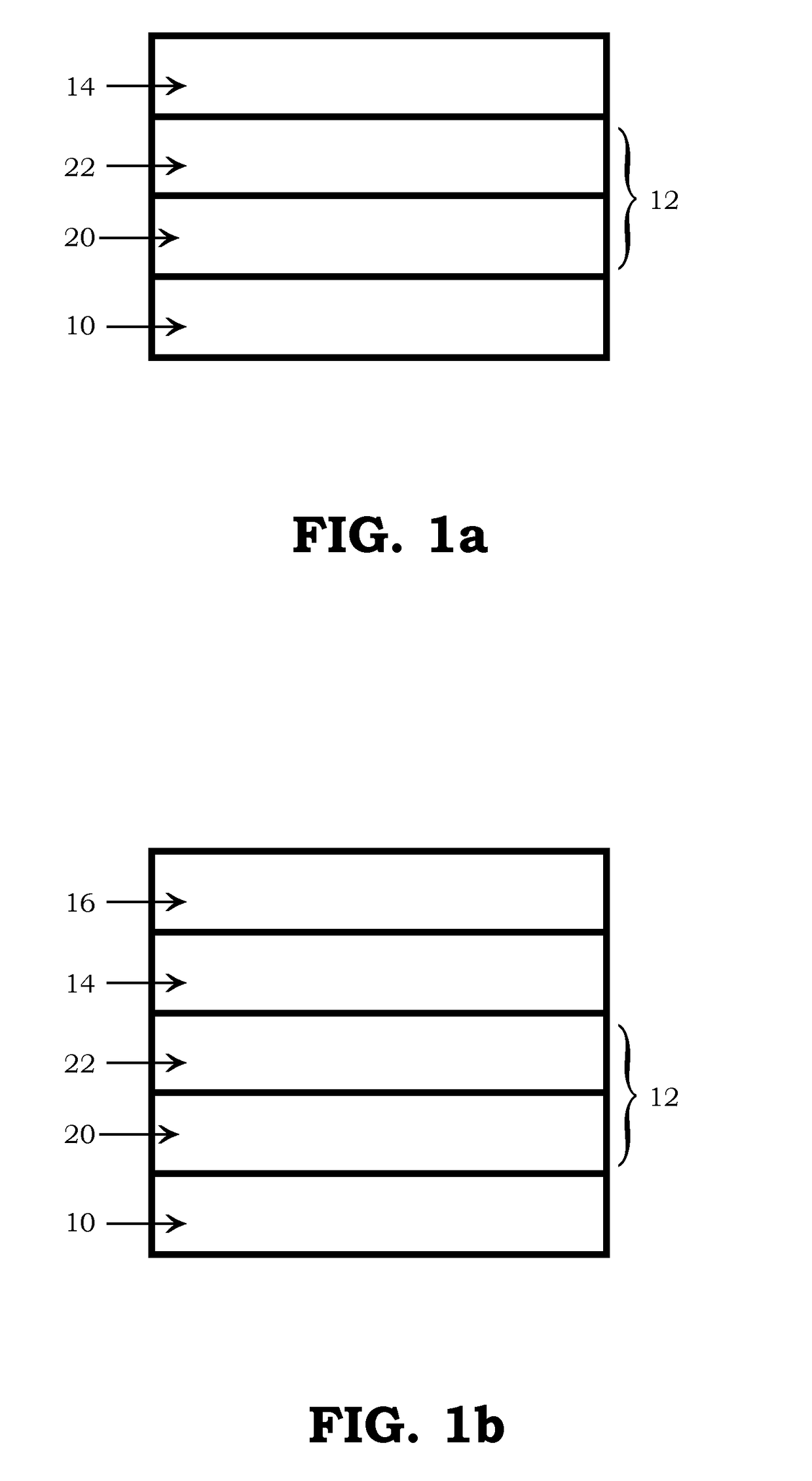
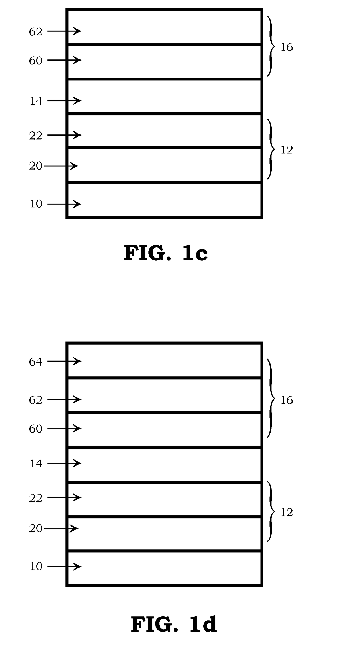
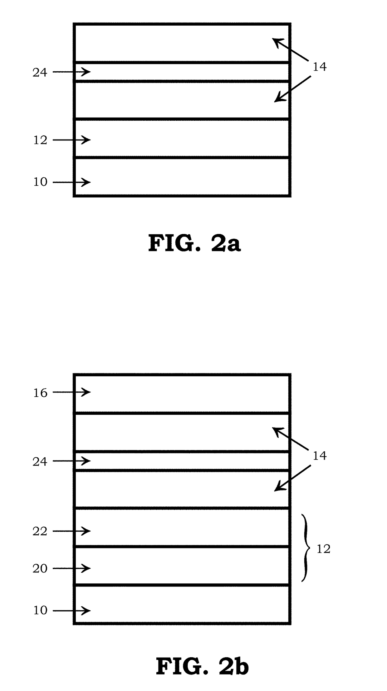
[0136]A glass substrate was coated with an underlayer, and a transparent conductive oxide layer. The underlayer had a first underlayer film and a second underlayer film. The first underlayer film was zinc stannate over the glass substrate, and the second underlayer film was a silica-alumina alloy having about 85 weight percent silica and 15 weight percent alumina over the first underlayer film. The transparent conductive oxide layer over the second underlayer film was tin-doped indium oxide (“ITO”).
[0137]In order to improve the conductivity of the coated article, the entire article was placed into a furnace and the temperature of the transparent conductive oxide layer was measured (see FIG. 7).
[0138]The following samples were tested to establish the improved conductivity for each thickness of ITO.
ITO ThicknessITO Surface Temp.Sheet ResistanceSample(nm)(° F.)(Ω / □)196.8Not flash annealed68.4296.843523.6396.863524.8496.880621.8596.887821.2696.896820.28105.2Not flash annealed67.28...
example 2
[0142]A glass substrate was coated with a transparent conductive oxide layer. The transparent conductive oxide was gallium-doped zinc oxide (“GZO”). Several samples with different GZO thicknesses were prepared and the sheet resistance measured for samples to compare the effects of post-deposition processing to the sheet resistance of GZO as deposited. The post-deposition process was placing the coated article in a furnace. The sheet resistance of each sample was tested before and after flash annealing, and the results are shown in FIG. 9. The thickness and sheet resistance for the samples test are listed in Table 3, below.
TABLE 3Samples from Example 2GZO ThicknessSheet ResistanceSheet ResistanceSample(nm)(as deposited)(flash annealed)116084.436.6232035.612.7340026.99.6448021.87.8564016.25.3680012.04.279607.62.7812009.93.5
[0143]As shown in FIG. 9, post-deposition flash annealing of the GZO improved the sheet resistance for all of the thicknesses tested. The improvement was most signi...
example 3
[0149]A glass substrate was coating an aluminum-doped zinc oxide (“AZO”) transparent conductive oxide layer. Several samples with different AZO thicknesses were prepared and the sheet resistance measured for samples to compare the effects of post-deposition processing to the sheet resistance of AZO as deposited. The post-deposition process involved placing the coated article in a furnace. The sheet resistance of each sample was tested before and after flash annealing, and the results are shown in FIG. 10. The thickness and sheet resistance for the samples test are listed in Table 4, below.
TABLE 4Samples from Example 3AZO ThicknessSheet ResistanceSheet ResistanceSample(nm)(as deposited)(flash annealed)1172166.046.9234478.319.5343058.414.5451648.112.2568835.38.6686026.67.17103217.03.9
[0150]As shown in FIG. 10, post-deposition heating of the AZO improved the sheet resistance for all of the thicknesses tested. The improvement was most significant when the AZO was approximately 344 to 86...
PUM
| Property | Measurement | Unit |
|---|---|---|
| Percent by mass | aaaaa | aaaaa |
| Percent by mass | aaaaa | aaaaa |
| Percent by mass | aaaaa | aaaaa |
Abstract
Description
Claims
Application Information