Method and apparatus for contrast enhanced photography of wind turbine blades

a technology of contrast enhancement and wind turbine blades, which is applied in image enhancement, instruments, machines/engines, etc., can solve the problems of false positives and false negatives, difficult non-destructive inspection of wind turbine blades, and inability to identify defects below the surface of the outer skin of the wind turbine blade, etc., to achieve high contrast, reduce glare, and high resolution

Active Publication Date: 2019-02-14
GE INFRASTRUCTURE TECH INT LLC
View PDF9 Cites 3 Cited by
  • Summary
  • Abstract
  • Description
  • Claims
  • Application Information

AI Technical Summary

Benefits of technology

[0011]In accordance with the embodiment described herein, a system for inspecting utility scale wind turbine generator blades from the ground for propagating subsurface anomalies during normal operation comprises a digital camera and an adjustable polarizing filter on a stable platform that is used to record multiple digital images with varying polarization angles during daylight hours. Images with the same or similar registration but different polarization angles are subsequently image processed using subtraction or absolute difference routines to yield high resolution, high contrast images with reduced glare and excellent surface definition over the field of view. Images of blades may be calibrated to determine the location, signal to noise ratio, size, or other quantitative measurements of anomalies, and such early detection may allow repair of the blade up tower instead of more costly replacement.

Problems solved by technology

Due to their large size, extensive surface area and complex shape, wind turbine blades are difficult to nondestructively inspect even within a fabrication or repair facility.
Visual inspection cannot identify defects below the surface of the outer skin of the wind turbine blade, which typically is fabricated from a fiberglass material.
Active thermography inspection techniques using heat are effective for near surface defects but can give false positives and false negatives due to variations in material thickness and surface emissivity.
Shearography with either thermal stress or during flexure testing of the blade in the factory can be used to detect fiberwaves in spar caps and other areas of the blade, but the technique is slow, expensive and is usually performed only if known issues are suspected.
Angle beam ultrasonic techniques are very slow and may not work through thick carbon fiber spar caps.
As a result, blades are commonly installed on towers and put into service with a significant probability of latent manufacturing defects.
Furthermore, composite blades are subject to extreme temperature variations.
Entrapped water in blades can undergo freeze / thaw cycles, which can cause internal damage.
Cyclic forces of gravity and varying forces from the wind acting on the blades as they rotate can cause fatigue damage or the propagation of latent defects over time while manufacturing process mistakes can lead to early blade failure.
Defects can grow below the surface of a wind turbine blade to the point that by the time cracks and damage breach the surface and can be detected visually, the damage may not be repairable on tower.
Detecting progressive damage and propagating defects in wind turbine blades in situ is difficult for a number of different reasons.
Inspectors using sky cranes or rope access are expensive, time consuming and put personnel in a very dangerous working environment.
Blade and tower crawlers with nondestructive testing sensors for in situ inspection have been developed and tested, but they can be extremely expensive, slow to operate.
Pixels may be saturated with glare or areas of the blade may be in shadows.
The normalization of the histogram, a frequent image processing function, may not be effective in achieving the effect of uniform blade illumination, except in small areas of the blade in the images.

Method used


Image

  • Method and apparatus for contrast enhanced photography of wind turbine blades
  • Method and apparatus for contrast enhanced photography of wind turbine blades
  • Method and apparatus for contrast enhanced photography of wind turbine blades

Examples


Embodiment Construction

[0022]Certain terminology is used in the following description for convenience only and is not limiting. The words “right”, “left”, “lower”, and “upper” designate directions in the drawings to which reference is made. The words “inwardly” and “outwardly” refer to directions toward and away from, respectively, the geometric center of the device and designated parts thereof. The terminology includes the above-listed words, derivatives thereof, and words of similar import. Additionally, the words “a” and “an”, as used in the claims and in the corresponding portions of the specification, mean “at least one.”

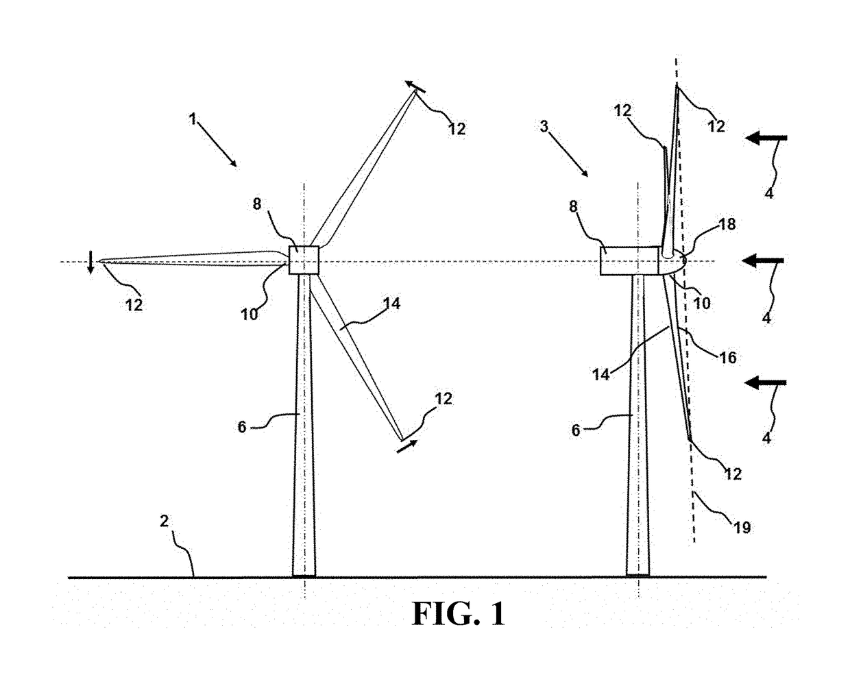
[0023]Referring now to the drawings, wherein like reference numerals indicate corresponding structure throughout the views, and referring in particular to FIG. 1, provided is a schematic diagram of a horizontal axis wind turbine (HAWT) that is typical of both land based and off-shore turbine generators. The view 1 from behind the turbine facing the wind includes tower 6 extending up ...


PUM


Abstract

A method and apparatus for inspecting utility scale wind turbine generator blades from the ground includes a digital camera and an adjustable polarizing filter on a stable platform. The camera is used to record multiple digital images with varying polarization angles using an artificial polarized or polarized solar illumination to produce images with the same or similar registration but different polarization angles, followed by image processing using subtraction or absolute difference routines to yield high resolution, high contrast images with reduced glare and excellent surface definition over the field of view.

Description

CROSS-REFERENCE TO RELATED APPLICATIONS[0001]This application claims the benefit of U.S. Provisional Patent Application No. 62 / 042,102, filed on Aug. 26, 2014, currently pending, entitled “Method and Apparatus Contrast Enhanced Photography of Wind Turbine Blades,” the entire contents of which are incorporated by reference herein.INCORPORATIONS BY REFERENCE[0002]Applicant hereby incorporates by reference, as if set forth fully herein, the entirety of the disclosures of U.S. patent application Ser. No. 13 / 731,085, filed Dec. 30, 2012, now U.S. Pat. No. 8,553,233, and having the title “Method and Apparatus for the Remote Nondestructive Evaluation of an Object,” U.S. patent application Ser. No. 13 / 837,145, filed on Mar. 15, 2013, and having the title “Method and Apparatus for Monitoring Wind Turbine Blades During Operation,” U.S. patent application Ser. No. 13 / 839,908, filed on Mar. 15, 2013, and having the title “System and Method for Ground Based Inspection of Wind Turbine Blades,” U....

Claims


Application Information

Patent Timeline
Patent Type & Authority Applications(United States)
IPC IPC(8): G06K9/62G06T7/62G06T7/00F03D17/00G06K9/52G06K9/46B60R11/04
CPCG06T7/62Y02E10/726G06T2207/30164G06T7/001F03D17/00G06T2207/20224G06K9/6215G06K9/52G06K9/4661B60R11/04G06T7/0004F05B2270/8041G01N21/9515G01N21/8806G01N2021/8848G01N2201/0616Y02E10/72G06F18/22
Inventor NEWMAN, JOHN W.
Owner GE INFRASTRUCTURE TECH INT LLC
Why Eureka
Try Eureka