
An Event-Based Vision Sensor

a technology of event-based vision and sensor, which is applied in the field of vision sensors, can solve the problems of high throughput of data motion blur, and high redundancy of sensor output data, and achieve the effects of low temporal resolution, high power consumption, and high redundancy of output data

Active Publication Date: 2019-02-14
SONY ADVANCED VISUAL SENSING AG
View PDF0 Cites 25 Cited by
  • Summary
  • Abstract
  • Description
  • Claims
  • Application Information

AI Technical Summary

Benefits of technology

The present invention is a vision sensor that can efficiently encode visual input and has multiple advantages including improved efficiency, greater temporal resolution, smaller pixel size, and reduced jitter in the readout path. The sensor uses a row-selection circuit to output the address of a pixel if the difference between the voltage output from the photoreceptor and the voltage across the first storage capacitor is greater than a predefined threshold voltage. The sensor can also have a high dynamic range and good low-light performance. Overall, the invention provides a better system-level performance and is well-suited for solar- or battery powered compressive sensing or for mobile machine vision applications where the position of the system has to be estimated and processing power is limited.

Problems solved by technology

While for some machine vision tasks like objection recognition these conventional cameras are well suited, for other tasks like tracking or position and motion estimation the conventional image sensors have drawbacks: these sensors produce a significant amount of redundant, unnecessary data that has to be captured, communicated and processed.
This high throughput of data slows down the reaction time, the temporal resolution and increases the power consumption, size and prize of a machine vision system.
In addition to these problems, most image sensors suffer from a limited dynamic range, poor low-light performance and motion blur.
These drawbacks limit the capabilities of the machine vision systems and arise from the fact that conventional image sensors have been developed to produce beautiful images and movies and not to generate smart data.
Finding these pairs of points that correspond to each other in both images is known as solving the “correspondence problem” and it requires a significant amount of processing power.
This first prior art sensor also circumvents the shortcomings mentioned above, but the pixel circuits used are complex and therefore require significant die area, which results in large sensor chips that require larger optics.
In this first prior art sensor, each pixel contains two comparators to detect changes and the necessary circuits to initiate the communication, which amounts to complex circuitry.
Additionally the prior art sensor works completely asynchronous, which makes interfacing standard processing hardware like microprocessors more cumbersome.
The sensor resets all pixels unconditionally of the change detection output, meaning that movements slower than the frame rate cannot be observed.
An additional disadvantage of the second prior art sensor is that it is a linear sensor and has thus limited dynamic range.

Method used


Image

  • An Event-Based Vision Sensor
  • An Event-Based Vision Sensor
  • An Event-Based Vision Sensor

Examples


example equations

for Logarithmic Photoreceptor:

[0201]As an example for better understanding, for the following equations it is assumed that the sensor stores a quantity that is proportional to the logarithm of the light intensity, because this is the preferred implementation.

[0202]A voltage encoding the light intensity is read at discretized times:

Vpr(tn)=k1+k2* log (Int(tn)),   (11)

[0203]where k1 and k2 are constants. To decide if an event has happened, we compute the difference between Vpr(tn) and Vpr at the time of the last event t1:

Vdiff(tn)=A(Vpr(tn)-Vpr(tl))=A*k2(log(Int(tn))-log(Int(tl))(12)Vdiff(tn)=A*k2*logInt(tn)Int(tl)(13)

[0204]We see that for a logarithmic intensity encoding, the sensor reacts to relative changes in the intensity, which is useful because it means the sensor reacts to scene reflectance changes independent of the illumination level which is the reason for being the preferred embodiment. From Erreur ! Source du renvoi introuvable., we see that

Vdiff(tn)=A∫tltnf′(Int(t))*dInt...


PUM


Abstract

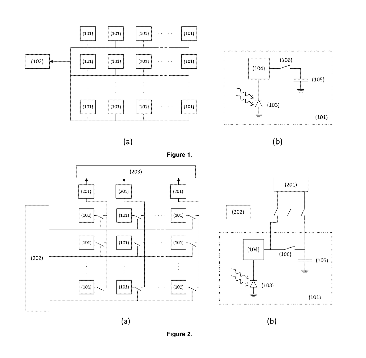
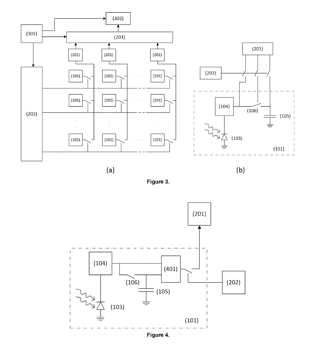
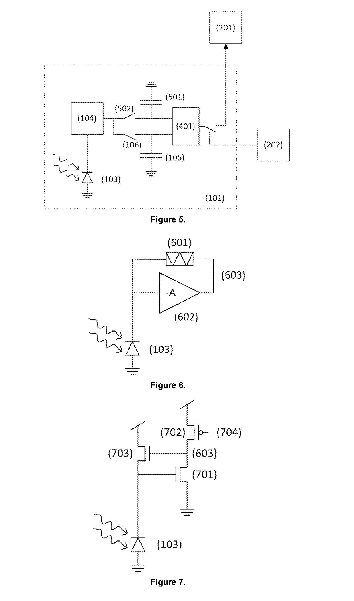
According to the present invention there is provided a vision sensor comprising, an array of pixels (101) comprising rows and columns of pixels, wherein each pixel has an address assigned thereto which represents the position of the pixel in the array, wherein each pixel in the array of pixels comprises a photodiode (103) which can receive light, and which can output current having an amplitude proportional to the intensity of the received light; a photoreceptor circuit (104) which is electronically connected to the photodiode, and which is configured to convert current which it receives from the photodiode into a voltage; a first storage capacitor (105), and at least a first switch which (106) is positioned between the first storage capacitor and an output of the photoreceptor circuit, wherein the first switch can be selectively closed to electronically connect the output of the photoreceptor circuit to the first storage capacitor, or selectively opened to electronically disconnect the output of the photoreceptor circuit from the first storage capacitor; and a circuit (102, 201) which is configured so that it can be selectively electronically connected to a pixel in the array, and to determine if the difference between the voltage output from the photoreceptor circuit and the voltage across the first storage capacitor is greater than a predefined threshold voltage, and to output the address of the pixel to a receiver only if the difference between the voltage output from the photoreceptor circuit and the voltage across the first storage capacitor is greater than a predefined threshold voltage. There is further provided a corresponding method of vision sensing using the vision sensor.

Description

FIELD OF THE INVENTION[0001]The present invention concerns a vision sensor for machine vision applications. The sensor reacts to changes in light intensity. In the vision sensor the addresses of those pixels where a light intensity change has been detected are output.DESCRIPTION OF RELATED ART[0002]Today machine vision is mostly based on conventional cameras and their associated frame-based image sensors. While for some machine vision tasks like objection recognition these conventional cameras are well suited, for other tasks like tracking or position and motion estimation the conventional image sensors have drawbacks: these sensors produce a significant amount of redundant, unnecessary data that has to be captured, communicated and processed. This high throughput of data slows down the reaction time, the temporal resolution and increases the power consumption, size and prize of a machine vision system. In addition to these problems, most image sensors suffer from a limited dynamic ...

Claims


Application Information

Patent Timeline
Patent Type & Authority Applications(United States)
IPC IPC(8): H04N5/351H04N5/3745H04N5/378H04N5/345
CPCH04N5/351H04N5/37452H04N5/378H04N5/345H04N25/771H04N25/47H04N25/707H04N25/50H04N25/44H04N25/75
Inventor BERNER, RAPHAEL
Owner SONY ADVANCED VISUAL SENSING AG
Learn More