
Oxygen evolution electrocatalysts with carbon coated cobalt (ii, iii) oxide layers

Inactive Publication Date: 2019-02-21
SABIC GLOBAL TECH BV
View PDF0 Cites 1 Cited by
  • Summary
  • Abstract
  • Description
  • Claims
  • Application Information

AI Technical Summary

Benefits of technology

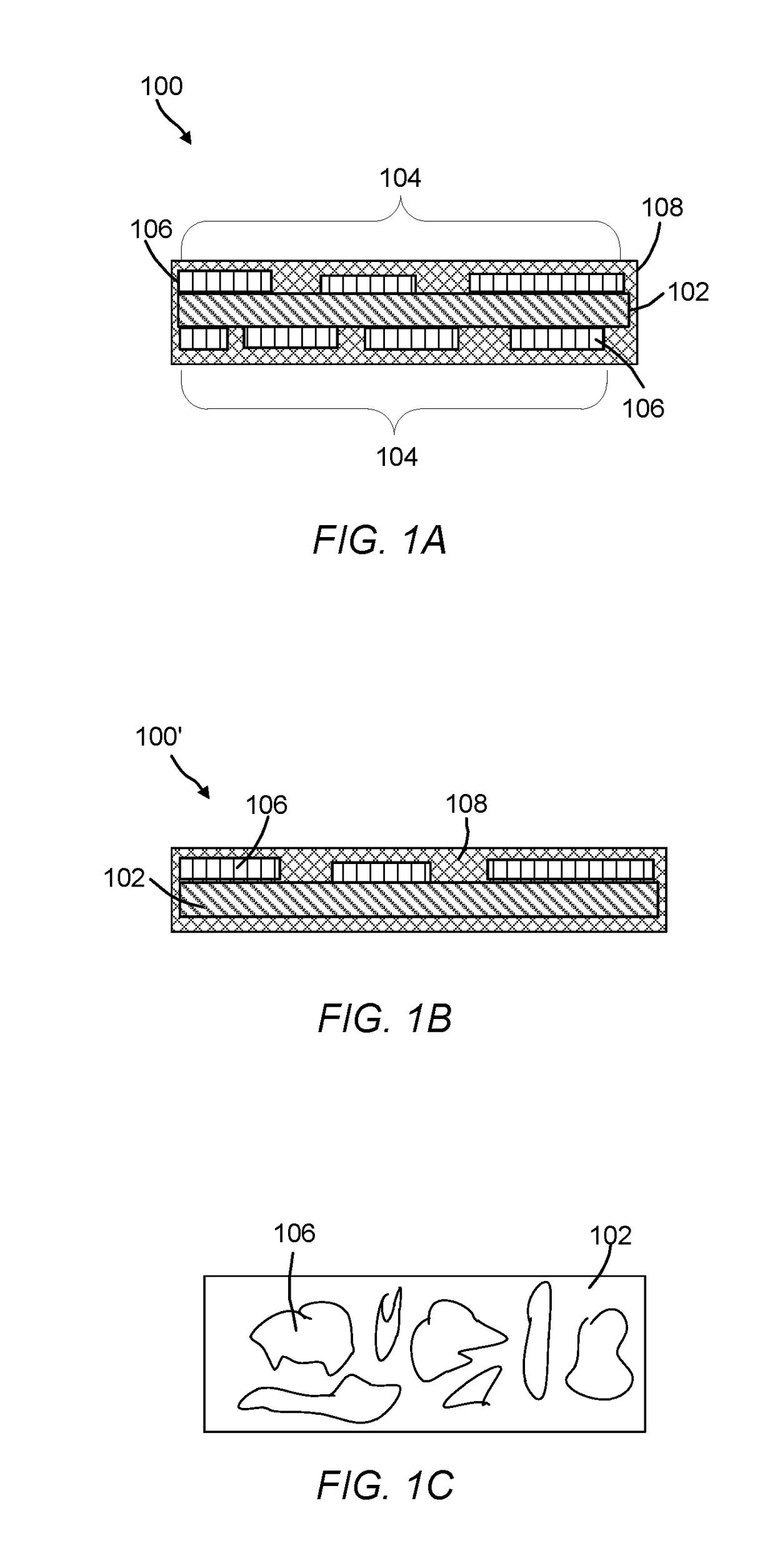
The patent text describes a new solution for using cobalt in electrodes for oxygen reduction reactions (OER), which is a problem that can occur in such reactions. The solution involves using a layer of discontinuous catalytic cobalt oxide (Co3O4) between a carbon support and an amorphous carbon layer. This structure allows for efficient charge transfer between the cobalt and the carbon support, while preventing the catalyst from exfoliating from the surface. This solution does not require the use of expensive precious metals and is stable in both acid and alkaline solutions. The technical effect of this discovery is an improved OER electrocatalyst that overcomes the problems associated with cobalt usage in such reactions.

Problems solved by technology

However, their scarce nature and associated high-cost considerably limit large-scale implementation of industrial devices.
Furthermore, these catalysts can be unstable in corrosive acids.
However, the development of alkaline water electrolysis has been restricted by several issues including low current density and cross-diffusion of the produced gases.
However, anodes made with these metals also suffered from corrosion during use.
Co3O4 has shown catalytic properties and chemical stability in alkaline solutions, however, the application of Co3O4 for OER in acidic medium has not been successful as the Co3O4 suffers from corrosion at potentials higher than 1.47 V (vs.
Furthermore, the cobalt OER electrodes suffer from poor adhesion of the Co3O4 to the electrode substrate (e.g., titanium foil substrates).
These electrodes suffer in that the charge flow to and from the cobalt core is inefficient due to the cobalt being isolated from the solution by two layers of carbon.
As discussed above, many of the OER catalysts currently available suffer from anodic corrosion in acidic environments, leaching of catalytic material from the support material, and / or manufacture of the OER catalyst is not cost effective.

Method used


Image

  • Oxygen evolution electrocatalysts with carbon coated cobalt (ii, iii) oxide layers
  • Oxygen evolution electrocatalysts with carbon coated cobalt (ii, iii) oxide layers
  • Oxygen evolution electrocatalysts with carbon coated cobalt (ii, iii) oxide layers

Examples


example 1

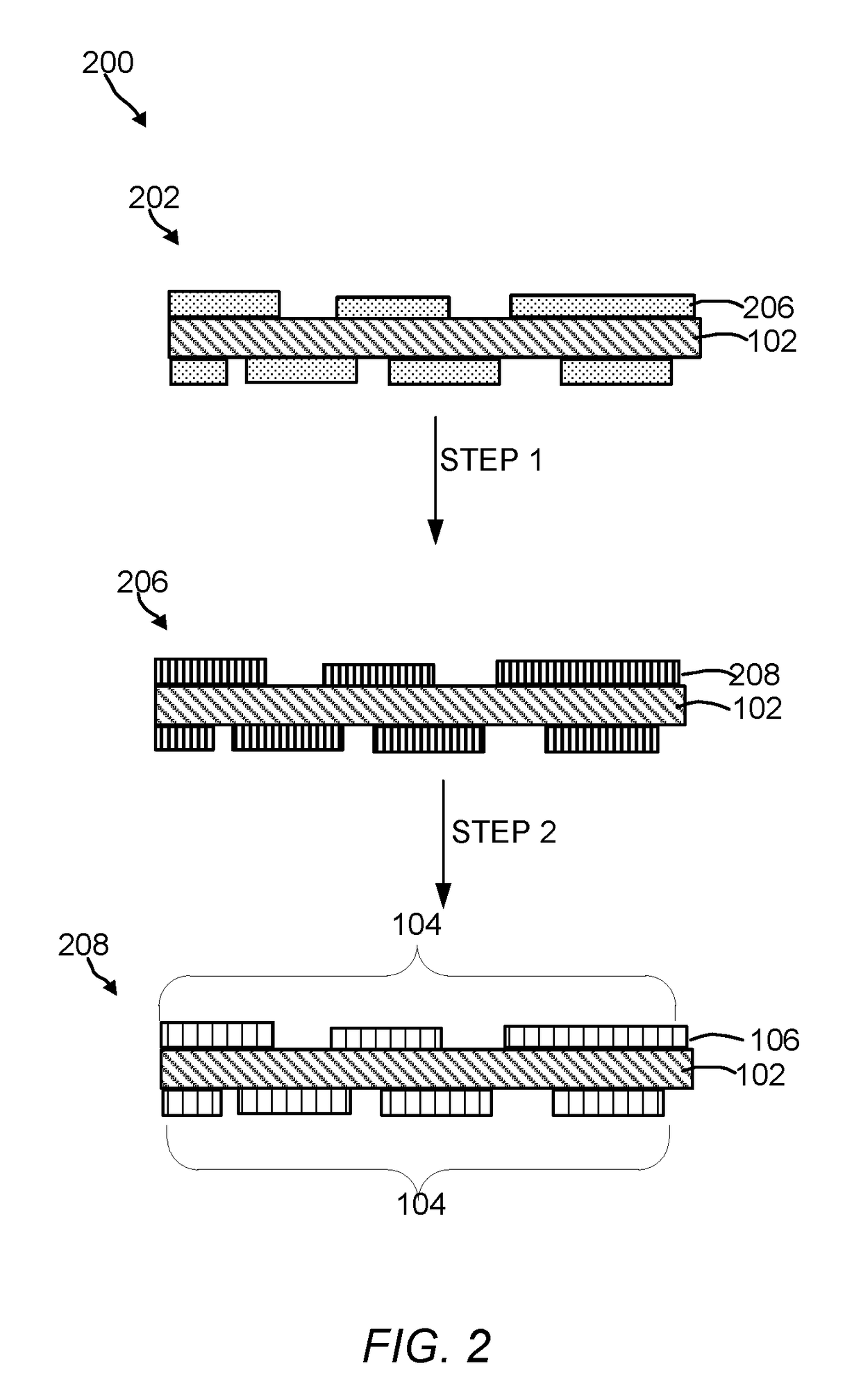
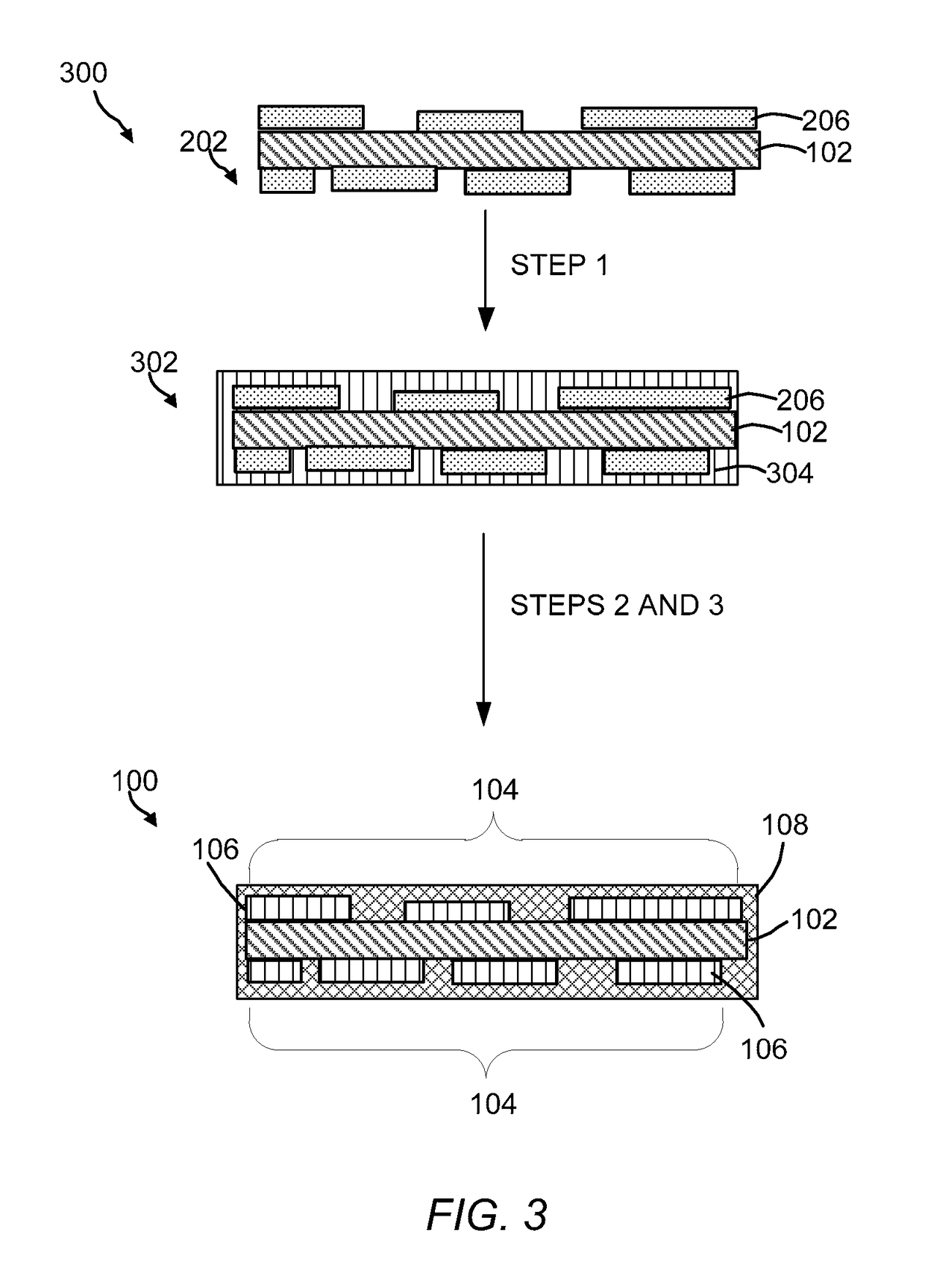
Preparation of OER Electrocatalyst of the Present Invention

[0071]Materials:

[0072]All chemical reagents including cobalt(II) nitrate hexahydrate, glucose, potassium hydroxide (KOH), sulfuric acid (H2SO4) and ethanol were purchased from Sigma Aldrich® (U.S.A.). Ultrapure water was obtained from a Millipore filtration system.

[0073]Electrochemical Deposition of Co-Species on Carbon Fiber Paper:

[0074]The carbon paper, 1 cm×2.5 cm) was first soaked with ethanol, and then oxidized in 0.5 M H2SO4 solution with cyclic voltammetry for 10 cycles between 1.5 to 2.3 V (vs. Ag / AgCl, in saturation KCl solution). The oxidized carbon paper (1 cm×1 cm) was then immersed into a 0.1 M Co(NO3)2 solution for the electrodeposition of Co-precursor. A Pt foil and an Ag / AgCl (in saturation KCl solution) electrode were used as the counter and reference electrodes respectively. Electrodeposition was performed at a constant current mode (−10 mA / cm2) from 10 to 60 min in a PGSTAT 302N Autolab workstation. The as...

example 2

Preparation of a Co3O4 / Carbon Paper OER Electrocatalyst

[0079]Co3O4 / carbon paper was prepared under the same experimental conditions used in Example 1 with the exception that carbon-containing layer was omitted. The Co3O4 catalyst loading amount on carbon paper (50 min) was determined to be 12.6 mg using a high precision weighing balance.

example 3

Preparation of OER Electrocatalyst Comparative Samples

CoO / Carbon Paper (Example 3A)

[0080]The cobalt precursor was deposited on carbon paper using the procedure in Example 1 and then heated under vacuum treatment for 1 hour to yield CoO / carbon paper.

Co3O4 / Carbon Paper (Example 3B)

[0081]The cobalt precursor was deposited on carbon paper using the procedure in Example 1, and then heated in air at 350° C. for 5 h to yield Co3O4 / carbon paper. The Co3O4 catalyst loading amount on carbon paper for Examples 3A and 3B was determined to be 12.6 mg±2 mg using a high precision weighing balance.

Preparation of Nafion Coated Co3O4 / Carbon Paper (Example 3C) and RuO2 / Carbon Paper (Example 3D)

[0082]The Co3O4 and RuO2 powder were prepared by directly annealing Co(NO3)2.6H2O and RuCl3 precursors in a porcelain boat and placed in a muffle furnace, and then heated to 350° C. with a ramp of 2.5° C. / min and maintained for 5 h in air. After that, the furnace was allowed to cool to room temperature. Nafion (...


PUM

PropertyMeasurementUnit
Thicknessaaaaaaaaaa
Thicknessaaaaaaaaaa
Thicknessaaaaaaaaaa

Abstract

Oxygen evolution reaction (OER) catalysts and uses thereof are described. An OER catalyst can include a carbon support, a discontinuous catalytic cobalt (II,III) oxide (Co3O4) nanolayer in direct contact with the carbon support, and an amorphous continuous carbon layer. The Co3O4 nanolayer is positioned between the carbon support and an amorphous continuous carbon layer.

Description

CROSS REFERENCE TO RELATED APPLICATIONS[0001]This application claims the benefit of priority of U.S. Provisional Patent Application No. 62 / 324,093 filed Apr. 18, 2016, which is hereby incorporated by reference in its entirety.BACKGROUND OF THE INVENTIONA. Field of the Invention[0002]The invention generally concerns oxygen evolution reaction (OER) electrocatalysts that includes a discontinuous catalytic Co3O4 nanolayer in direct contact with a carbon support and an amorphous continuous carbon layer. The discontinuous Co3O4 catalytic nanolayer is between the carbon support and the amorphous continuous carbon layer.B. Description of Related Art[0003]Use of hydrogen as an energy source has increased with the needed minimize CO2 emission from fossil fuels. One source of hydrogen can be from the splitting of water into hydrogen and oxygen. Water splitting can be achieved on a large scale using an electrochemical apparatus (e.g., electrolyzer). In an electrolyzer, water is split into hydro...

Claims


Application Information

Patent Timeline
IPC IPC(8): C25B11/04C25B1/04
CPCC25B11/0478C25B1/04C25B11/0415B01J23/75B01J33/00Y02E60/36C25B11/057C25B11/091B01J35/30B01J35/33
Inventor LI, LAIN-JONGYANG, XIULINIDRISS, HICHAM
Owner SABIC GLOBAL TECH BV
Learn More