
Semiconductor device for power supply control and power supply device, and discharging method for x capacitor

Inactive Publication Date: 2019-03-07
MITSUMI ELECTRIC CO LTD
View PDF1 Cites 13 Cited by
  • Summary
  • Abstract
  • Description
  • Claims
  • Application Information

AI Technical Summary

Benefits of technology

The patent describes a new configuration for a semiconductor device used in power supply control. The main benefits are that it reduces power consumption during standby mode by quickly discharging residual charges in the circuit, and it eliminates the need for a separate circuit for discharging. The device also includes a peak holding circuit, which helps determine the timing of discharging. Additionally, the device includes multiple voltage comparison circuits that allow for a more accurate detection of voltage peaks and off mode power consumption. Overall, this new configuration improves the efficiency and accuracy of power supply control in semiconductor devices.

Problems solved by technology

The AC-DC converter including the resistor for discharging which is connected in parallel with the X capacitor, however, always consumes power during the connection to the AC power supply.
Therefore, the standby power consumption at the time of load not being applied and at the time of standby is increased.
Since an AC-DC converter as a power supply device incorporated in such electronic equipment does not stop its operation as long as the cord is plugged in, there is a problem that the power consumption during standby is large.
It is known that the standby power consumption of the AC-DC converter has an extremely high proportion of current consumption of the primary-side control IC.
However, there is a problem that the power consumption is large since the number of circuits is large, and the chip size is increased since elements having large occupying areas such as capacity of the peak holding circuit and a diode are used.
However, in the invention described in Japanese Patent Application Laid Open Publication No. 2016-158399, there is a problem that the power consumption during standby is not sufficiently reduced due to operations of the internal power supply circuit, the circuit for starting the IC, the circuit for controlling the starting, the discharging circuit of the X capacitor, the reference voltage circuit and the bias circuit in the standby mode.
However, if operation of the discharging circuit for the X capacitor is stopped in the standby mode in order to reduce the power consumption, there is a problem that it is not possible to detect the removal of the plug to perform discharging of the X capacitor in the standby mode.

Method used


Image

  • Semiconductor device for power supply control and power supply device, and discharging method for x capacitor
  • Semiconductor device for power supply control and power supply device, and discharging method for x capacitor
  • Semiconductor device for power supply control and power supply device, and discharging method for x capacitor

Examples


modification example

[0096]In the power supply control IC in the embodiment, the off mode is maintained by continuing to receive the off mode signal from the microcomputer or the like on the secondary side with the photo transistor 15c. However, there may be provided a toggle flip-flop (T-FF) which inverts the output at each time of pulse input to the back part of the off detection comparator 61, so that shift to the off mode and return from the off mode to the normal mode are performed by receiving the off mode signal of one shot from the microcomputer or the like on the secondary side.

[0097]In a case where the Zener voltage of Zener diode ZD is a potential which is different from the internal power supply voltage generated by the internal power supply circuit 71, at the time of shift to the off mode, each of the reference voltages of the off detection comparator 61 and the comparators inside the discharging control circuit 42 generated in the resistance voltage division circuit 43 shifts from the pote...


PUM


Abstract

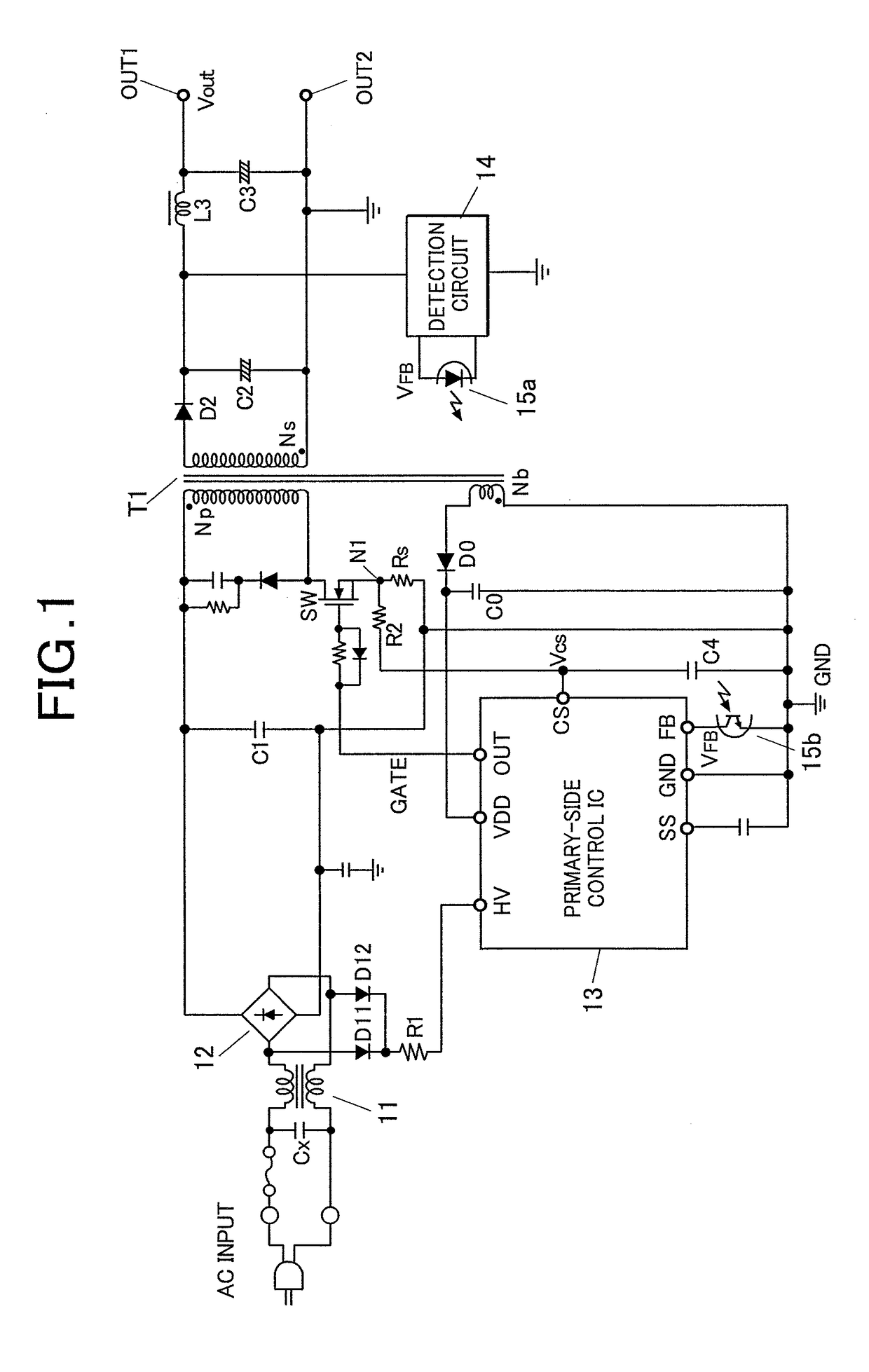
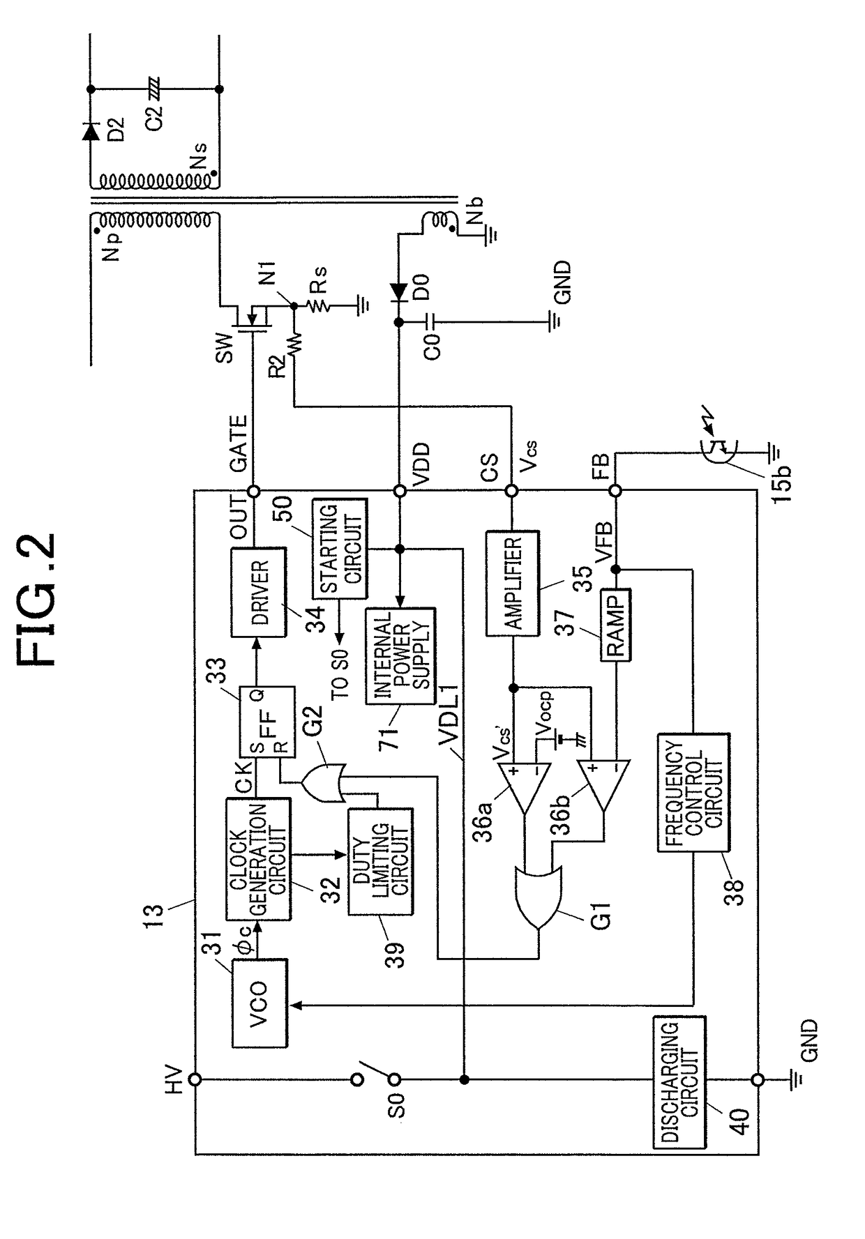
A semiconductor device for power supply control generating and outputting a driving pulse for performing control to turn on / off a switching element by inputting voltage in proportion to current in the primary-side winding wire and an output voltage detection signal from a secondary side, the device including: a high-voltage input start terminal to which alternating-current voltage of AC input or rectified voltage is input; voltage comparison circuits to which voltage obtained by dividing voltage input to the high-voltage input start terminal is input and which compare the input voltage with any of reference voltages; a timer circuit which starts to measure a predetermined time at a timing of rising and / or falling of output of the voltage comparison circuits; and a discharging unit between the high-voltage input start terminal and a ground point, wherein the discharging unit is made conductive when the predetermined time is measured.

Description

BACKGROUND OF THE INVENTION1. Field of the Invention[0001]The present invention relates to a semiconductor device for power supply control, and particularly to a technique which is effectively used in a semiconductor device for primary-side control that is included in an insulated direct-current power supply device provided with a transformer for voltage conversion.2. Description of Related Art[0002]Examples of direct-current power supply devices include an insulated AC-DC converter which is structured by, for example, a diode bridge circuit that rectifies an alternating-current power supply, a DC-DC converter that reduces the direct-current voltage rectified in the diode bridge circuit to convert the voltage into a direct-current voltage of a desired potential and the like.[0003]In a general insulated AC-DC converter, an X capacitor is connected between AC terminals in order to attenuate the normal-mode noise and a resistor for discharging is connected in parallel with the X capaci...

Claims


Application Information

Patent Timeline
IPC IPC(8): H02M1/32H02M3/335H02M1/08
CPCH02M1/32H02M3/33507H02M1/08H02M2001/322H02M2001/0032H02M3/33523H02M7/219Y02B70/10H02M1/0032H02M1/322
Inventor MATSUDA, HIROKI
Owner MITSUMI ELECTRIC CO LTD
Learn More