Eureka AIR delivers breakthrough ideas for toughest innovation challenges, trusted by R&D personnel around the world.

Catalyst and method for preparing the same

a catalyst and catalyst technology, applied in the field of catalysts and methods for preparing the same, can solve the problems of slow oxygen reduction reaction in the cathode, low catalyst utilization rate, and low catalyst utilization rate, and achieve the effects of increasing the catalyst utilization rate of the electrode layer, increasing the degree of dispersion of alloy particles, and high activity

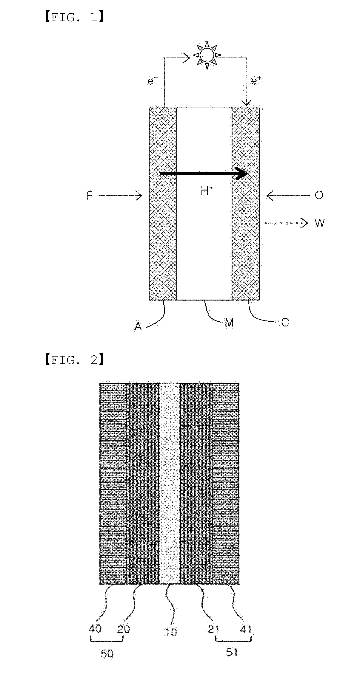
Active Publication Date: 2019-03-21
LG CHEM LTD
View PDF0 Cites 2 Cited by
  • Summary
  • Abstract
  • Description
  • Claims
  • Application Information

AI Technical Summary

Benefits of technology

This patent describes a new method for making a catalyst for fuel cells that has a high activity for oxygen reduction. The method involves treating a carrier with an amine group and a hydrogen transfer ion layer, which increases the dispersion of alloy particles and improves the efficiency of the catalyst. The method is also environmentally friendly and simple. The resulting catalyst helps to lower hydrogen transfer resistance and improve fuel cell performance.

Problems solved by technology

As a fuel cell catalyst, platinum (Pt) is known to be most superior, however, high price and instability of platinum are factors inhibiting PEMFC commercialization.
Moreover, a slow oxygen reduction reaction in a cathode reduces fuel cell efficiency.
A colloidal synthesis method most commonly used in the art synthesizing such catalysts has an advantage in readily controlling catalyst particle sizes and shapes, but has a disadvantage in that activity decreases by catalyst reaction sites being blocked due to a surfactant adsorbed on the particle surface, and electron migration between a catalyst and a support is difficult.
However, there is a disadvantage in that particle shapes are difficult to control.

Method used


Image

  • Catalyst and method for preparing the same
  • Catalyst and method for preparing the same
  • Catalyst and method for preparing the same

Examples


example 1

[0156]After sufficiently dispersing 64.8 mg of the carbon coated with PEI and nafion of Preparation Example 1 into 25 mL of ethylene glycol, 66.9 mg of platinum(II) acetylacetonate (Pt(acac)2), 43.7 mg of nickel(II) acetylacetonate (Ni(acac)2) and 96.9 mg citric acid were added thereto, and the result was sufficiently stirred.

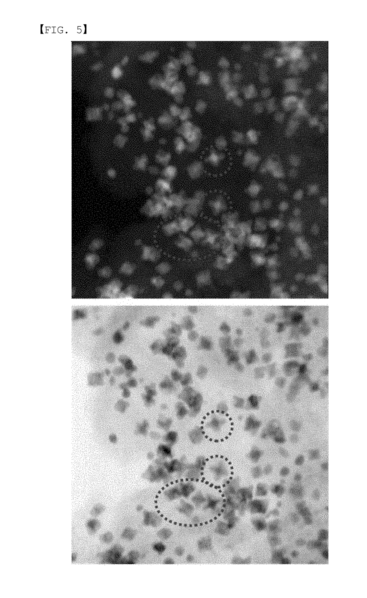
[0157]In order to remove water, the temperature was raised to 120° C. under vacuum, and the result was heated for 30 minutes, and after the temperature was raised to 200° C. under nitrogen atmosphere, the result was heated for 2 hours and 30 minutes. Herein, octahedron structured metal particles were formed during a synthesis process of raising the temperature from 120° C. to 200° C. and heating.

[0158]The result was cooled to room temperature, and then filtered using ethanol and distilled water. The filtered octahedron structured PtNi-carbon complex was dried in an oven, and placed in a 0.5 M sulfuric acid solution. The result was heated for 2 hours at 80° C., ...

example 2

[0159]After sufficiently dispersing 58.5 mg of the carbon coated with PEI and nafion of Preparation Example 1 into 30 mL of ethylene glycol, 78.7 mg of platinum(II) acetylacetonate (Pt(acac)2), 51.4 mg of nickel(II) acetylacetonate (Ni(acac)2) and 115.3 mg of citric acid were added thereto, and the result was sufficiently stirred.

[0160]In order to remove water, the temperature was raised to 120° C. under vacuum, and the result was heated for 30 minutes, and after the temperature was raised to 200° C. under nitrogen atmosphere, the result was heated for 2 hours and 30 minutes. Herein, octahedron structured metal particles were formed during a synthesis process of raising the temperature from 120° C. to 200° C. and heating.

[0161]The result was cooled to room temperature, and then filtered using ethanol and distilled water. The filtered octahedron structured PtNi-carbon complex was dried in an oven, and placed in a 0.5 M sulfuric acid solution. The result was heated for 2 hours at 80° ...


PUM

PropertyMeasurementUnit
timeaaaaaaaaaa
pHaaaaaaaaaa
weight ratioaaaaaaaaaa

Abstract

The present specification relates to a carrier-nanoparticle complex, a catalyst including the same, an electrochemical cell or a fuel cell including the catalyst, and a method for preparing the same.

Description

TECHNICAL FIELD[0001]The present disclosure claims priority to and the benefits of Korean Patent Application No. 10-2016-0155102, filed with the Korean Intellectual Property Office on Nov. 21, 2016, the entire contents of which are incorporated herein by reference.[0002]The present specification relates to a catalyst including a carrier-nanoparticle complex, an electrochemical cell or a fuel cell including the catalyst, and a method for preparing the same.BACKGROUND ART[0003]A polymer electrolyte membrane fuel cell (PEMFC) is a most promising alternative energy source due to its high energy density, low operating temperature, and environmental-friendly products. As a fuel cell catalyst, platinum (Pt) is known to be most superior, however, high price and instability of platinum are factors inhibiting PEMFC commercialization. Moreover, a slow oxygen reduction reaction in a cathode reduces fuel cell efficiency.[0004]In view of the above, studies on preparing an alloy catalyst made of p...

Claims


Application Information

Patent Timeline
Patent Type & Authority Applications(United States)
IPC IPC(8): H01M8/1004H01M4/92
CPCH01M8/1004H01M4/921H01M4/926H01M2004/8689H01M2008/1095B01J37/12B01J31/16B01J37/02H01M8/1018H01M4/90H01M4/9008H01M4/9083H01M4/92Y02E60/50B01J37/0219B01J31/165Y02P70/50
Inventor CHOI, RANKIM, SANG HOONHWANG, GYO HYUNCHO, JUN YEONKIM, KWANGHYUNLEE, WONKYUN
Owner LG CHEM LTD
Why Eureka
Eureka Blog
Learn More