Processors and methods for configurable clock gating in a spatial array

a technology of spatial array and processor, applied in the field of electrical devices, can solve the problems of high energy cost, out-of-order scheduling, and inability to achieve simultaneous multi-threading, and achieve the effect of improving the performance and energy efficiency of program execution with classical von neumann architectures

Inactive Publication Date: 2019-04-04
INTEL CORP
View PDF22 Cites 47 Cited by
  • Summary
  • Abstract
  • Description
  • Claims
  • Application Information

AI Technical Summary

Benefits of technology

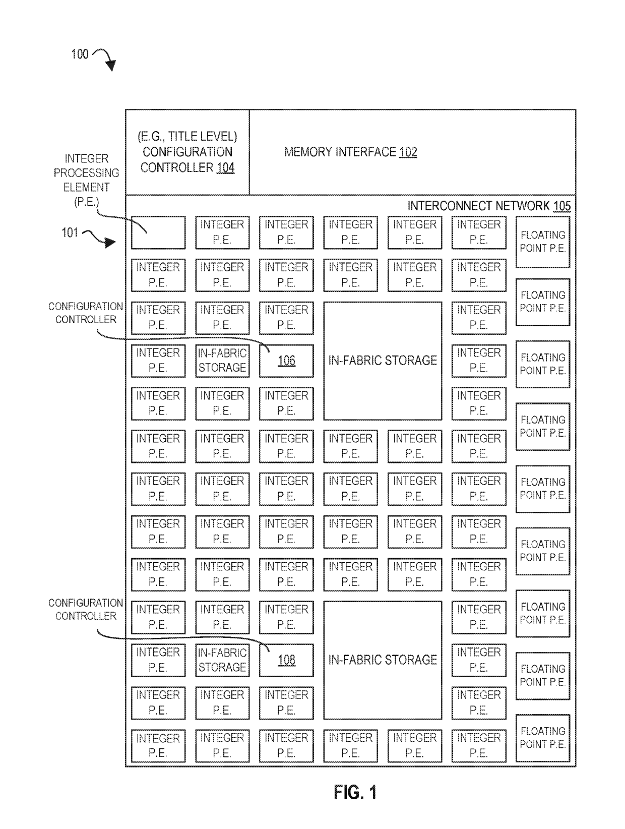
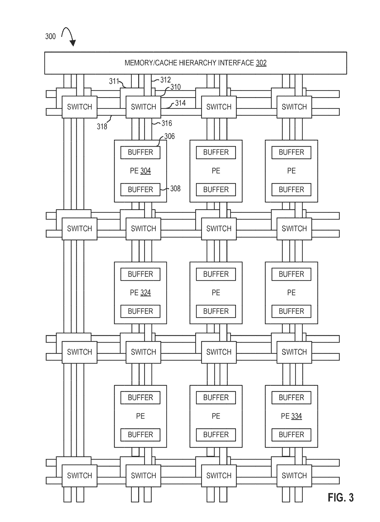
[0348]Supercomputing at the ExaFLOP scale may be a challenge in high-performance computing, a challenge which is not likely to be met by conventional von Neumann architectures. To achieve ExaFLOPs, embodiments of a CSA provide a heterogeneous spatial array that targets direct execution of (e.g., compiler-produced) dataflow graphs. In addition to laying out the architectural principles of embodiments of a CSA, the above also describes and evaluates embodiments of a CSA which showed performance and energy of larger than 10× over existing products. Compiler-generated code may have significant performance and energy gains over roadmap architectures. As a heterogeneous, parametric architecture, embodiments of a CSA may be readily adapted to all computing uses. For example, a mobile version of CSA might be tuned to 32-bits, while a machine-learning focused array might feature significant numbers of vectorized 8-bit multiplication units. The main advantages of embodiments of a CSA are high performance and extreme energy efficiency, characteristics relevant to all forms of computing ranging from supercomputing and datacenter to the internet-of-things.

Problems solved by technology

Exascale computing goals may require enormous system-level floating point performance (e.g., 1 ExaFLOPs) within an aggressive power budget (e.g., 20 MW).
However, simultaneously improving the performance and energy efficiency of program execution with classical von Neumann architectures has become difficult: out-of-order scheduling, simultaneous multi-threading, complex register files, and other structures provide performance, but at high energy cost.
In HPC systems as an example, power may be one of the major limiting factors in performance and / or design.
However, channels involving unconfigured PEs may be disabled by the microarchitecture, e.g., preventing any undefined operations from occurring.
Mismatch may mean that the data is from the wrong epoch and needs to wait.
However, enabling real software, especially programs written in legacy sequential languages, requires significant attention to interfacing with memory.
However, embodiments of the CSA have no notion of instruction or instruction-based program ordering as defined by a program counter.
Exceptions in a CSA may generally be caused by the same events that cause exceptions in processors, such as illegal operator arguments or reliability, availability, and serviceability (RAS) events.
For example, in spatial accelerators composed of small processing elements (PEs), communications latency and bandwidth may be critical to overall program performance.
Although runtime services in a CSA may be critical, they may be infrequent relative to user-level computation.
However, channels involving unconfigured PEs may be disabled by the microarchitecture, e.g., preventing any undefined operations from occurring.
However, by nature, exceptions are rare and insensitive to latency and bandwidth.
Packets in the local exception network may be extremely small.
While a program written in a high-level programming language designed specifically for the CSA might achieve maximal performance and / or energy efficiency, the adoption of new high-level languages or programming frameworks may be slow and limited in practice because of the difficulty of converting existing code bases.
It may not be correct to simply connect channel a directly to the true path, because in the cases where execution actually takes the false path, this value of “a” will be left over in the graph, leading to incorrect value of A for the next execution of the function.
In contrast, von Neumann architectures are multiplexed, resulting in large numbers of bit transitions.
In contrast, von Neumann-style cores typically optimize for one style of parallelism, carefully chosen by the architects, resulting in a failure to capture all important application kernels.
Were a time-multiplexed approach used, much of this energy savings may be lost.
The previous disadvantage of configuration is that it was a coarse-grained step with a potentially large latency, which places an under-bound on the size of program that can be accelerated in the fabric due to the cost of context switching.
Embodiments of a CSA may not utilize (e.g., software controlled) packet switching, e.g., packet switching that requires significant software assistance to realize, which slows configuration.
As a result, configuration throughput is approximately halved.
Thus, it may be difficult for a signal to arrive at a distant CFE within a short clock cycle.
For example, when a CFE is in an unconfigured state, it may claim that its input buffers are full, and that its output is invalid.
Thus, the configuration state may be vulnerable to soft errors.
As a result, extraction throughput is approximately halved.
Thus, it may be difficult for a signal to arrive at a distant EFE within a short clock cycle.
In an embodiment where the LEC writes extracted data to memory (for example, for post-processing, e.g., in software), it may be subject to limited memory bandwidth.
Supercomputing at the ExaFLOP scale may be a challenge in high-performance computing, a challenge which is not likely to be met by conventional von Neumann architectures.
This converted code is not likely to be the same as the alternative instruction set binary code 6310 because an instruction converter capable of this is difficult to make; however, the converted code will accomplish the general operation and be made up of instructions from the alternative instruction set.

Method used


Image

  • Processors and methods for configurable clock gating in a spatial array
  • Processors and methods for configurable clock gating in a spatial array
  • Processors and methods for configurable clock gating in a spatial array

Examples


Embodiment Construction

[0087]In the following description, numerous specific details are set forth. However, it is understood that embodiments of the disclosure may be practiced without these specific details. In other instances, well-known circuits, structures and techniques have not been shown in detail in order not to obscure the understanding of this description.

[0088]References in the specification to “one embodiment,”“an embodiment,”“an example embodiment,” etc., indicate that the embodiment described may include a particular feature, structure, or characteristic, but every embodiment may not necessarily include the particular feature, structure, or characteristic. Moreover, such phrases are not necessarily referring to the same embodiment. Further, when a particular feature, structure, or characteristic is described in connection with an embodiment, it is submitted that it is within the knowledge of one skilled in the art to affect such feature, structure, or characteristic in connection with other...


PUM


Abstract

Methods and apparatuses relating to configurable clock gating in spatial arrays are described. In one embodiment, a processor includes processing elements; an interconnect network between the processing elements; and a configuration controller, coupled to a first processing element and a second processing element of the plurality of processing elements and the first processing element having an output coupled to an input of the second processing element, to configure the second processing element to clock gate at least one clocked component of the second processing element, and configure the first processing element to send a reenable signal on the interconnect network to the second processing element to reenable the at least one clocked component of the second processing element when data is to be sent from the first processing element to the second processing element.

Description

STATEMENT REGARDING FEDERALLY SPONSORED RESEARCH AND DEVELOPMENT[0001]This invention was made with Government support under contract number H98230A-13-D-0124-0202 awarded by the Department of Defense. The Government has certain rights in this invention.TECHNICAL FIELD[0002]The disclosure relates generally to electronics, and, more specifically, an embodiment of the disclosure relates to circuitry for configurable clock gating in a spatial array.BACKGROUND[0003]A processor, or set of processors, executes instructions from an instruction set, e.g., the instruction set architecture (ISA). The instruction set is the part of the computer architecture related to programming, and generally includes the native data types, instructions, register architecture, addressing modes, memory architecture, interrupt and exception handling, and external input and output (I / O). It should be noted that the term instruction herein may refer to a macro-instruction, e.g., an instruction that is provided to...

Claims


Application Information

Patent Timeline
Patent Type & Authority Applications(United States)
IPC IPC(8): G06F1/08G06F1/10G06F1/32G06F9/38G06F15/80
CPCG06F1/08G06F1/10G06F1/3237G06F9/3869G06F9/384G06F9/3802G06F15/8023G06F1/14G06F9/3867G06F9/4403G06F1/3243G06F9/4494G06F15/825Y02D10/00
Inventor DIAMOND, MITCHELLKEEN, BENJAMINFLEMING, JR., KERMIN E.
Owner INTEL CORP
Why Eureka
Try Eureka