
Method and system for detecting and locating single-phase ground fault on low current grounded power-distribution network

a single-phase ground fault, low-current technology, applied in the field of low-current single-phase ground fault detection and location methods and systems, can solve the problems of no effective method, large majority of failures are single-phase ground, and the main power grid is short-circuit and ground faul

Inactive Publication Date: 2019-05-09
BEIJING INHAND NETWORKS TECH
View PDF4 Cites 28 Cited by
  • Summary
  • Abstract
  • Description
  • Claims
  • Application Information

AI Technical Summary

Benefits of technology

The present invention aims to provide an effective system for detecting and locating low current single-phase ground faults in a timely and accurate manner. The invention includes a signal synchronization module which uses wireless communication network timing and GPS timing to synchronize the pickup of voltage and current signals on the feeder. Overall, this synchronization enables accurate detection and location of ground faults, improving operational efficiency and reliability.

Problems solved by technology

A common fault in the main power grid is short circuit and ground fault.
But for single-phase ground fault detection, especially for low current grounded distribution network single-phase ground, there is no effective method, and is recognized as a worldwide problem.
Therefore, the vast majority of failures are single-phase ground.
However, single-phase ground fault must be found as quickly as possible during single-phase ground fault troubleshooting.
Otherwise, the over voltage caused by the failure of the ground fault can cause the cable to explode, the voltage transformer PT to burn down, the bus to burn and other power system accidents.
If not fixed in time, long-running ground fault will burden local residents, livestock with tremendous security risks.
Thus in a low current grounded method with a single-phase ground fault, the detection and location is recognized as a worldwide problem.
The main disadvantages of the low current grounded line selection device are:(1) The existing substation PT (voltage transformer) and CT (current transformer) affect the reliability and accuracy of the selected line.
Selection device is subject to PT ferromagnetic resonance, and it will cause significant interference.
Because factors such as the special zero-sequence CT volume, high cost, and the need to install power, for low current grounded line selection device to obtain zero sequence current is not usually obtained through special zero-sequence CT, but by a substation having three-phase or two-phase measurements obtained with CT.
Therefore, due to the actual CT usually having angular error and phase change error, resulting in an unbalanced three-phase CT.
Also the three-phase CT superposition of zero-sequence current is an unbalanced current, and the actual zero-sequence current errors exist, that would impact of the line election results.
In practice, the mid to low voltage grid frequently exhibits the CT saturation phenomenon, causing failure in getting the correct zero sequence current in performing line selection.
Moreover, the core maintains energy storage cycle and magnetizing cycle, which makes CT transient characteristics not satisfactory.
When current changes are not properly followed, it is difficult to accurately capture weak transient signals.(2) The location of the ground fault cannot be accurately located.
Low current grounded line can only be installed in power distribution bus to sub location, and only for selecting a ground fault in the branch line.
It is not capable to locate the position of branch line where the ground fault occurs.
(1) It requires the installation of the signal source in the substation, therefore, changing the system operation;
(2) The signal sources and other devices require additional investment and construction, and the construction process requires a power outage;
(3) For ground fault at the common resistance of 800Ω or more, this method was unable to produce a sufficient large coded signal current to be detectable by fault indicator, therefore, this method cannot detect high-resistance ground fault;
(4) It cannot detect transient ground faults.
The main disadvantages of the FTU network based ground fault detection and location method is:
(2) In measuring CT, it would be difficult to capture the transient signals; also it would be facing high current saturation; and during the three-phase superimposed zero-sequence, phase imbalance is causing large errors; these are factors making high resistance grounded difficult to be detected;
(3) PT has ferromagnetic resonance problem;
(4) Installing switch and FTU needs power lines to be offline;
(5) It can only locate the fault up to between switches, but not more in terms of accurate positioning;
(6) For overhead line to provide power to the FTU is very difficult, negatively affecting its installation and functioning.
At present time, the low current grounded system, especially the neutral point Petersen coil grounded system, the lack of effective ground fault detection methods and equipment makes it hard to detect the ground fault position.
These methods are of low degree of automation, are difficult and inefficient to implement, and are unable to meet the requirements of the power system to continue to improve the reliability of power supply.
These methods are also making it difficult to improve power quality and power supply reliability.

Method used


Image

  • Method and system for detecting and locating single-phase ground fault on low current grounded power-distribution network
  • Method and system for detecting and locating single-phase ground fault on low current grounded power-distribution network
  • Method and system for detecting and locating single-phase ground fault on low current grounded power-distribution network

Examples


Embodiment Construction

[0113]Below in connection with the accompanying figures of the present invention embodiment, the present invention will be apparent in the technical implementation of the invention. The described embodiments are only part of the present invention, but not all. The described embodiments of the present invention, and all other embodiments perceived by those of ordinary skill in creativity, all belong to the scope of the present invention.

[0114]Below with references to the figures, the present invention is further described in detail.

[0115]An embodiment of the present invention is to provide a low current single-phase ground fault detection and location, as shown in FIG. 6, comprising:

[0116]At step 61, data collections were made to voltage and current signals for each of a plurality of positions in the feeder;

[0117]Specifically at set intervals, periodically the voltage and current signals on each phase feeders are collected at the plurality of positions, or they can be collected at sp...


PUM


Abstract

A method and system for detecting and locating a single-phase ground fault on a low current grounded power-distribution network, comprising: respectively testing and picking up the voltage signals and current signals at multiple positions on each phase feeder (61), and determining the corresponding transient voltage signals and transient current signals according to the extraction of the voltage signals and the current signals (62); when the change in the transient voltage signals and the transient current signals exceeds a preset threshold (63), synchronously picking up the voltage signals and current signals at multiple positions on a three-phase feeder (64); calculating corresponding zero-sequence voltages and zero-sequence currents according to the voltage signals and current signals synchronously picked up at multiple positions on the three-phase feeder (65), and then extracting the steady-state signal and transient signal of the zero-sequence voltage and zero-sequence current at each position on the three-phase feeder (66); and determining a specific fault location on a faulty line according to the steady-state signal and the transient signal (67). The method effectively detects and displays a single-phase ground fault on a low current grounded power-distribution network.

Description

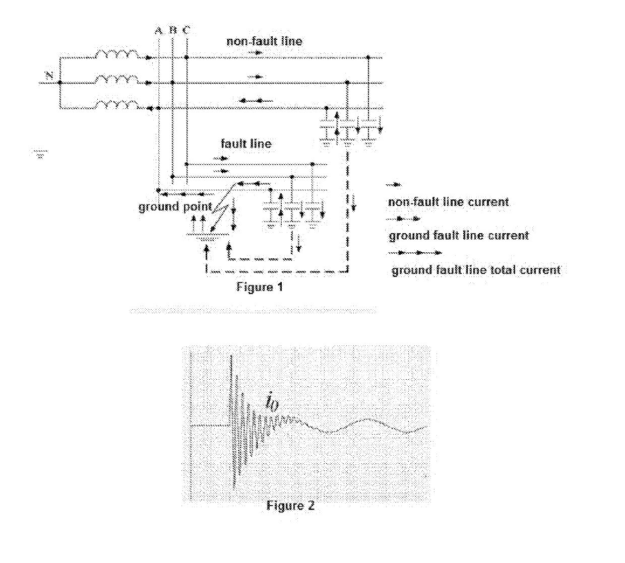
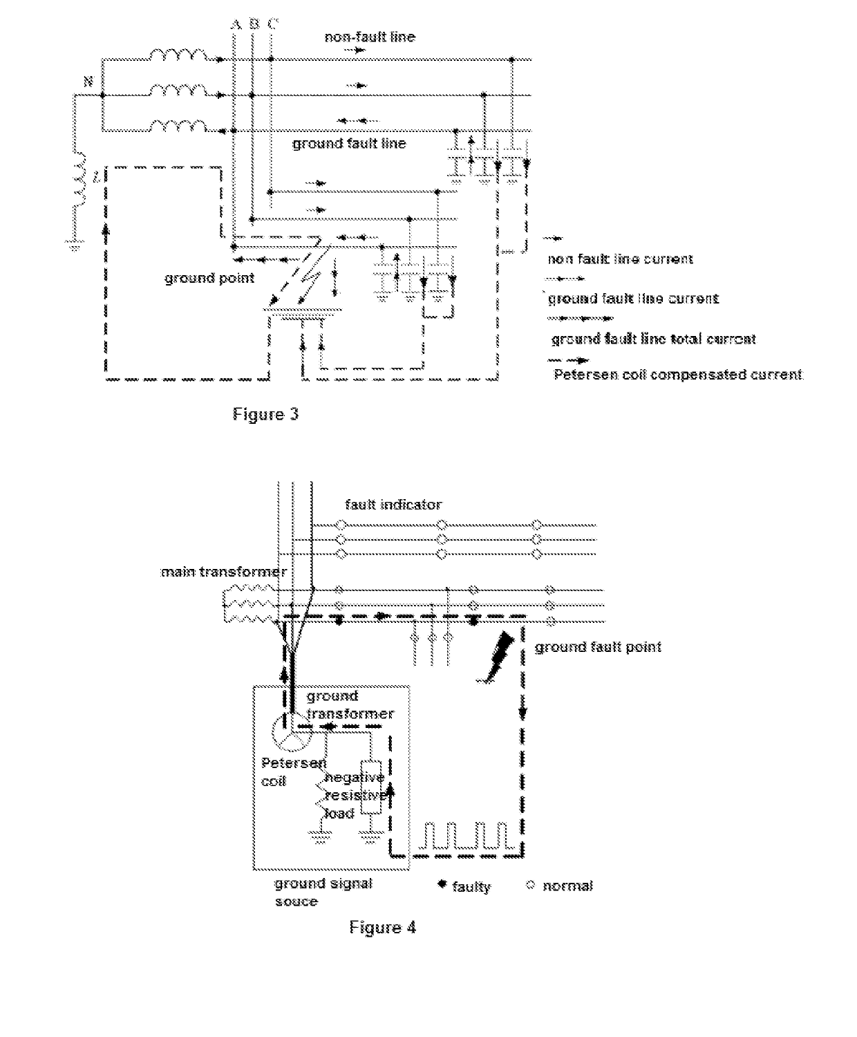
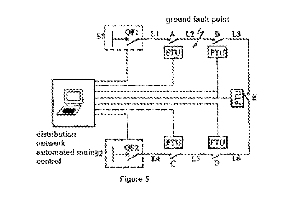
CROSS REFERENCES TO RELATED APPLICATIONS[0001]This application is a divisional of application Ser. No. 14 / 774,123, filed in the US Patent Office on Sep. 9, 2015, the entire contents of which are identical as follows. No new matter is added.BACKGROUND OF THE INVENTION[0002]The present invention relates to the field of electronic technology, particularly to a low current single-phase ground fault detection and location methods and systems.[0003]Power system contains power supply from power plants. Power is transferred to the load side first by high or extra high voltage transmission network, and then by the lower voltage levels of distribution network.[0004]A common fault in the main power grid is short circuit and ground fault. Short circuit faults include three-phase and two-phase short circuit faults. A common ground fault type is a single-phase ground. Short circuit fault detection technology has been very mature. But for single-phase ground fault detection, especially for low cur...

Claims


Application Information

Patent Timeline
Patent Type & Authority Applications(United States)
IPC IPC(8): G01R29/18G01R15/14H02H7/26G01R31/08G01R31/02H02H3/38
CPCG01R29/18G01R15/142H02H7/26G01R31/086G01R31/025H02H3/38G01R31/08Y04S10/522G01R31/52Y04S10/52
Inventor TANG, XIANWUZHANG, JIANLIANGLI, JINAOZANG, HONGWEI
Owner BEIJING INHAND NETWORKS TECH
Learn More