Core-shell particles, magneto-dielectric materials, methods of making, and uses thereof

Inactive Publication Date: 2019-07-18
ROGERS CORP
View PDF0 Cites 17 Cited by
  • Summary
  • Abstract
  • Description
  • Claims
  • Application Information

AI Technical Summary

Benefits of technology

[0007]Disclosed herein is a magneto-dielectric material comprising a polymer matrix and a plurality of the magnetic particl

Problems solved by technology

However, these materials are not entirely satisfactory in that they often do not provide the desired b

Method used


Image

  • Core-shell particles, magneto-dielectric materials, methods of making, and uses thereof
  • Core-shell particles, magneto-dielectric materials, methods of making, and uses thereof
  • Core-shell particles, magneto-dielectric materials, methods of making, and uses thereof

Examples


examples

[0084]In the examples, the magnetic particles were prepared by mixing raw powders of Fe and Ni in a polyurethane jar with Φ3 mm stainless steel balls for 2 to 24 hours. In accordance with the parameters set forth in Table 1, the mixed powder was then fed to a radio-frequency (RF) induction thermal plasma system by a carrier gas of argon and hydrogen, introduced to a plasma jet, and then cooled using a quenching gas of argon to form a plurality of particles. The particles were then collected in the collection chamber.

TABLE 1Processing ParametersValuePower of thermal plasma30 kilowattsVoltage of thermal plasma10.5 kilovoltsCurrent of thermal plasma3.5 AmpereCentral gas, Ar2.0 meters cubed per hourSheath gas, Ar2.0 meters cubed per hourCooling gas, Ar2.0 meters cubed per hourCarrier gas, H250 to 100 liters per hourCarrier gas, Ar100 to 150 meters cubed per hour

[0085]In order to determine the electromagnetic properties of the magnetic particles, the magnetic particles were mixed with pa...

examples 1-4

of Magnetic Particles

[0086]Four samples of magnetic particles were prepared by varying the combined feed rate of the iron and nickel powder into the plasma chamber. Feed rates of 0.5 grams per minute (g / min), 1 g / min, 2 g / min, and 5 g / min for mixed Ni and Fe powders were used to form the magnetic particles of Examples 1-4, respectively, and resulted in magnetic Fe66Ni34 particles having an average particle sizes of 50 nm, 70 nm, 100 nm, and 120 nm.

[0087]Specific values of the relative permeability (μ′), the magnetic loss tangent (tan(δμ)), the specific magnetic loss tangent (tan(δμ) / μ′), and the relative permittivity (E′), at different frequencies as well as the resonance frequency (fr) are shown in Table 2.

TABLE 2Example1234FrequencyParticle size (nm)50701001201 GHzμ′1.941.833.393.37tanδμ0.1730.1540.3810.312tanδμ / μ′0.0890.0840.1120.093ε′251950452 GHzμ′1.931.832.832.77tanδμ0.0630.0730.4380.400tanδμ / μ′0.0330.040.1550.144ε′241853443 GHzμ′1.691.632.382.25tanδμ0.0730.0830.5180.486tanδμ / ...

examples 5 and 6

0 nm Core-Shell Magnetic Particles

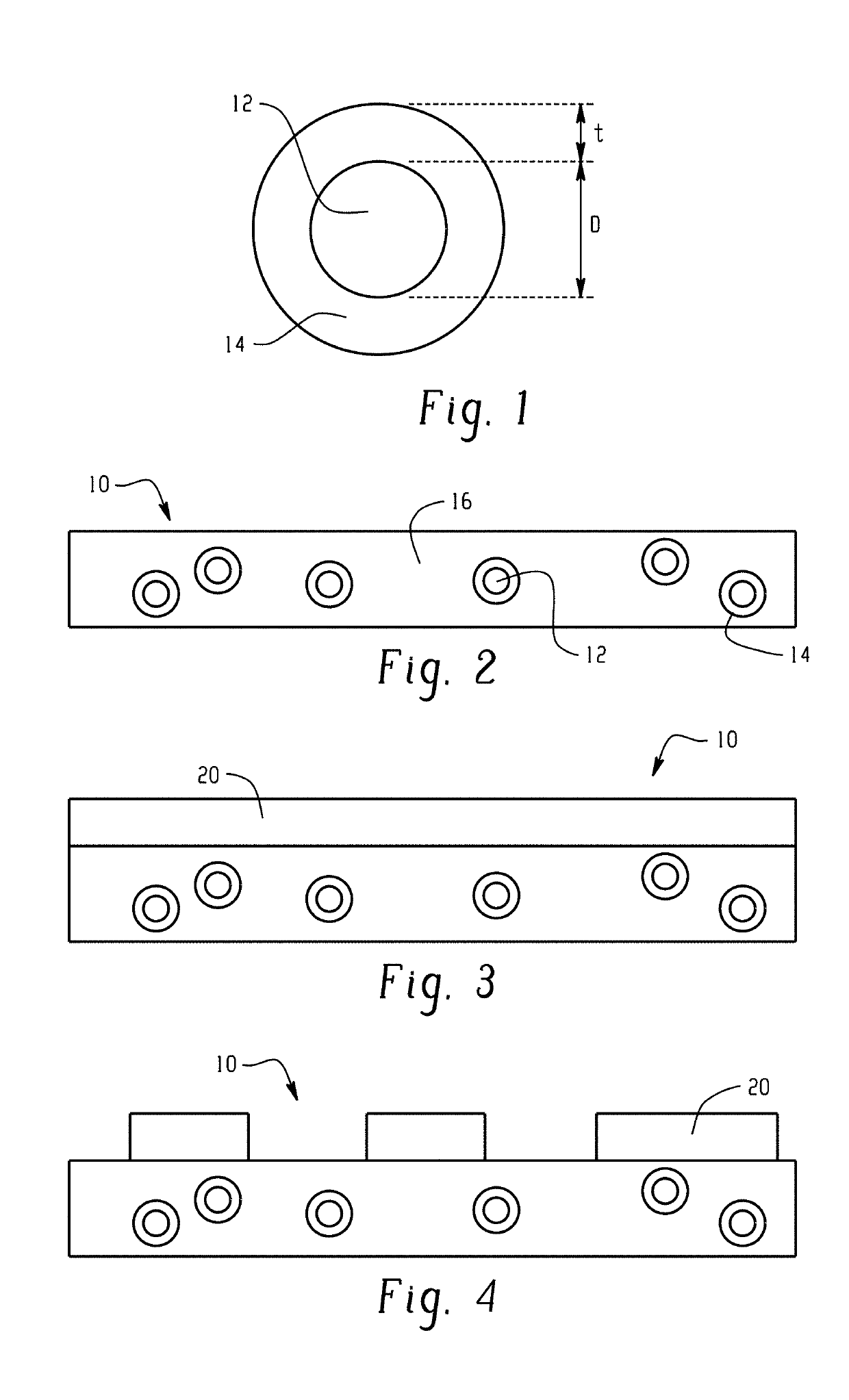
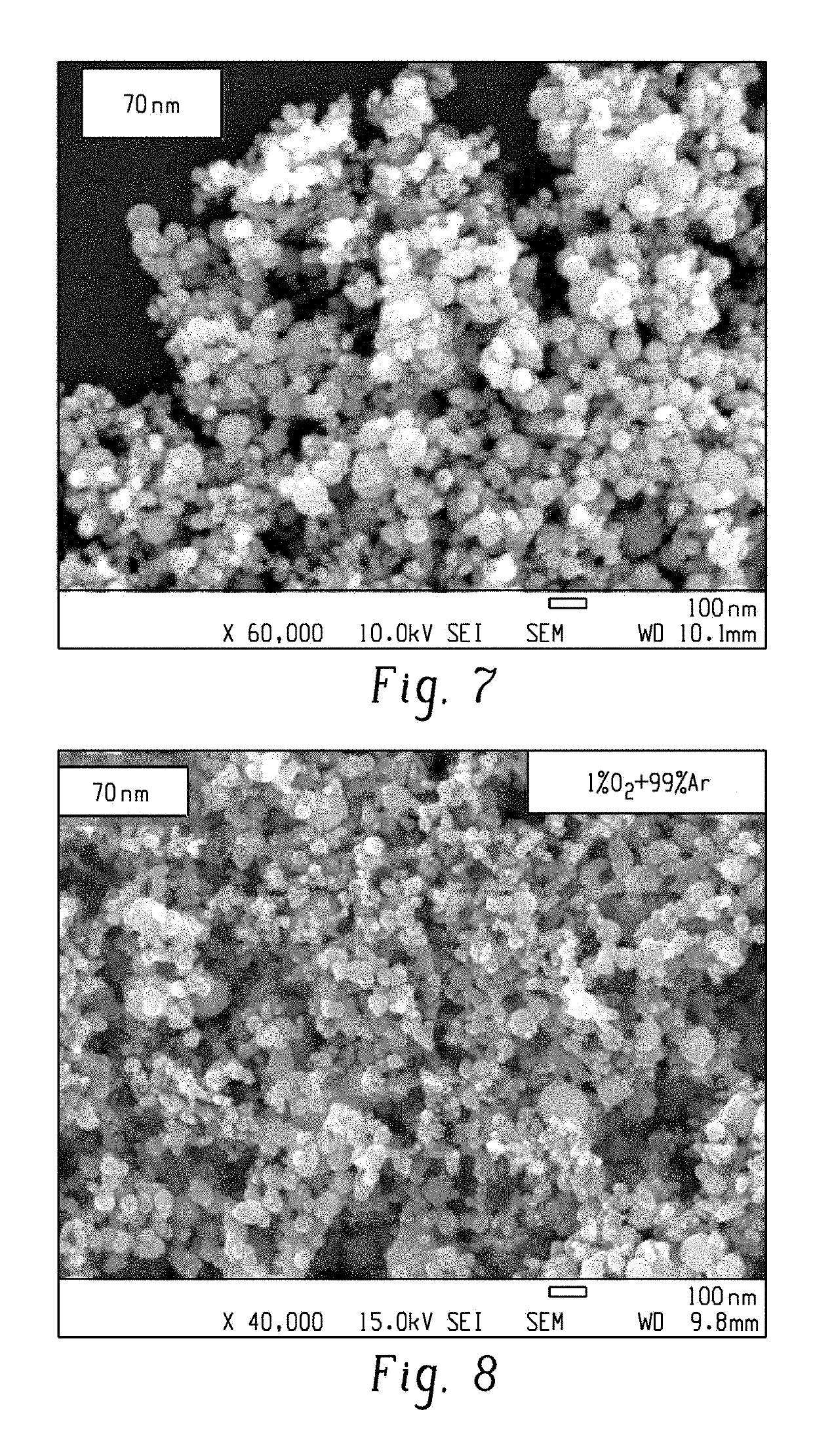
[0088]The particles of Example 2 having an average particle size of 70 nm were annealed in a low oxygen environment of 1 volume percent oxygen in argon at 500° C. for 30 minutes to form the shell on the nanoparticles. The resulting core-shell nanoparticles had a shell with a thickness of 2 to 50 nanometers. FIG. 7 and FIG. 8 are scanning electron microscopy images of the particles before and after annealing in oxygen, respectively.

[0089]The electromagnetic properties of the core-shell magnetic particles were then determined for the particles of Example 2 and Example 5 as described above. In Example 6, the electromagnetic properties of the same core-shell magnetic particles of Example 5 were determined, but using toroids comprising 60 volume percent of the core-shell magnetic particles.

[0090]The real (μ′) and imaginary (μ″) parts of the permeability for unannealed magnetic particles are shown in FIG. 9 for the magnetic particles of Example 2 and the ...


PUM

PropertyMeasurementUnit
Thicknessaaaaaaaaaa
Thicknessaaaaaaaaaa
Thicknessaaaaaaaaaa

Abstract

In an aspect, a magnetic particle, comprises a core comprising iron, and a second metal comprising cobalt, nickel, or a combination thereof; wherein a core atomic ratio of the iron to the second metal is 50:50 to 75:25; and a shell at least partially surrounding the core, and comprising an iron oxide, an iron nitride, or a combination thereof, and the second metal. In another aspect, a magneto-dielectric material comprises a polymer matrix and a plurality of the magnetic particles; wherein the magneto-dielectric material has a magnetic loss tangent of less than or equal to 0.07 at 1 GHz.

Description

CROSS REFERENCE TO RELATED APPLICATION[0001]This application claims the benefit of U.S. Provisional Patent Application Ser. No. 62 / 617,661 filed Jan. 16, 2018. The related application is incorporated herein in its entirety by reference.BACKGROUND[0002]This disclosure relates generally to core-shell particles, magneto-dielectric materials, methods of making, and uses thereof.[0003]Newer designs and manufacturing techniques have driven electronic components to increasingly smaller dimensions, for example, components such as inductors on electronic integrated circuit chips, electronic circuits, electronic packages, modules, housings, and antennas. One approach to reducing electronic component size has been the use of magneto-dielectric materials as substrates. In particular, ferrites, ferroelectrics, and multiferroics have been widely studied as functional materials with enhanced microwave properties. However, these materials are not entirely satisfactory in that they often do not prov...

Claims


Application Information

Patent Timeline
IPC IPC(8): H01F1/33H01F1/147B22F1/00B22F1/02H01F1/00C01G49/02B22F1/054B22F1/17
CPCH01F1/33H01F1/1475B22F1/0018B22F1/025H01F1/0054C01G49/02B82Y25/00B82Y30/00B82Y40/00C01P2006/42H01F1/0027H01F1/26B22F1/054B22F1/17
Inventor CHEN, YAJIESPRENTALL, KARL EDWARDPANCE, KRISTI
Owner ROGERS CORP
Why Eureka
Try Eureka