
Full-laser scribing method for flexible stainless steel substrate solar cell module

Active Publication Date: 2019-08-01
BEIJING SIFANG CRENERGEY OPTOELECTRONICS TECH CO LTD +1
View PDF4 Cites 1 Cited by
  • Summary
  • Abstract
  • Description
  • Claims
  • Application Information

AI Technical Summary

Benefits of technology

The present invention provides a full-laser scribing method for a flexible stainless steel substrate solar cell module that can complete all three scribes of a CIGS thin-film solar cell to realize inner connection of sub-cells of a solar cell module. The laser has the characteristics of stable operation, long service life, and the like, reducing the maintenance cost of the equipment. The method can reduce power loss of the module after scribing, ensure high processing efficiency, reduced consumption of raw materials, and low production cost. The use of screen printing in the traditional method is not necessary, increasing the production efficiency of the module and reducing the production and maintenance costs. The dead zone area of the module is reduced efficiently, improving the module power of the CIGS thin-film solar cell.

Problems solved by technology

Energy crisis and environmental pollution are two fundamental problems the world is facing now.
The disadvantage of this method lies in that the area of a dead zone accounts for 7% of an entire cell, and the efficiency loss of the module is very high; at the same time, the screen printing process is complicated, has poor process reproducibility and is costly due to high consumption of silver paste; therefore, if the rigid substrate full-laser scribing method (Application No.
However, in the case of a flexible stainless steel substrate, a Mo layer may be scribed off after P1 scribing, and it cannot form the insulating between cells because the stainless steel substrate is conductive.

Method used


Image

  • Full-laser scribing method for flexible stainless steel substrate solar cell module
  • Full-laser scribing method for flexible stainless steel substrate solar cell module
  • Full-laser scribing method for flexible stainless steel substrate solar cell module

Examples


embodiment 1

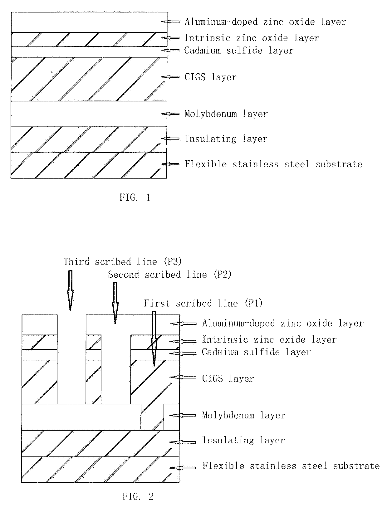
[0030]FIG. 1 shows the structure of the flexible stainless steel substrate CIGS thin-film solar cell according to the present invention. As shown in FIG. 1, the cell includes a stainless steel substrate, an insulating layer, a molybdenum layer, a CIGS layer, a cadmium sulfide layer, an intrinsic zinc oxide layer and an aluminum-doped zinc oxide layer.

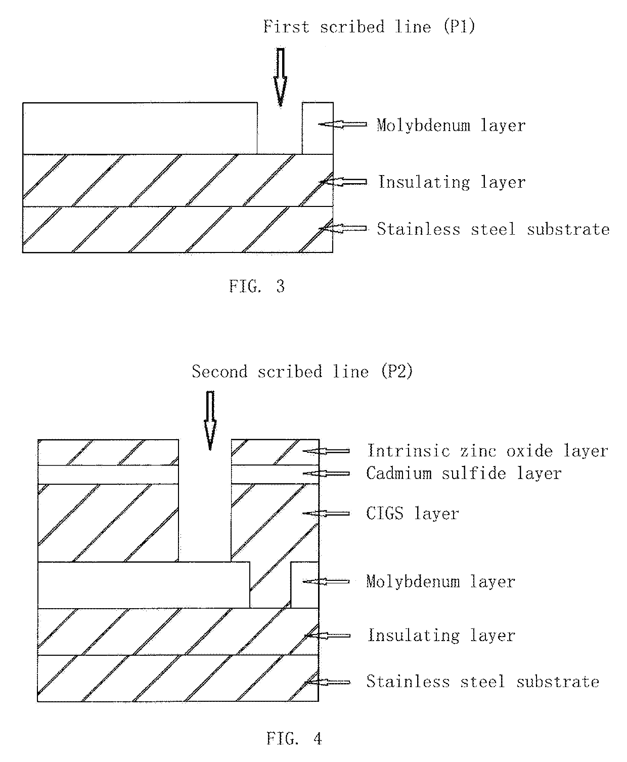
[0031]FIG. 2 shows a full-laser scribing method for the flexible stainless steel substrate CIGS thin-film solar cell according to the present invention. As shown in FIG. 2, the full-laser scribing method comprises laser scribing of three scribed lines: first, preparing an insulating layer and a molybdenum film on a flexible stainless steel substrate, and using a laser I to scribe off the prepared molybdenum film to form a first scribed line (P1), wherein the first scribed line (P1) scribes off the molybdenum layer on the insulating layer without damaging the insulating layer, laser is focused by a focusing lens and then is subjected to ...

embodiment 2

[0044]Step 1: an insulating layer is prepared on a flexible stainless steel substrate in the same way as Embodiment 1.

[0045]Step 2 is the same as that in Embodiment 1.

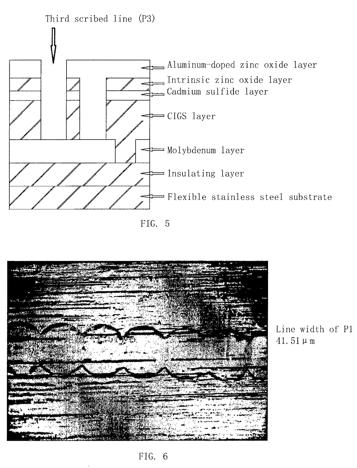
[0046]Step 3: scribing of P1: a sub-nanosecond laser with pulse width of 800 picoseconds, wavelength of 532 nm, scribing power of 2.7 W, single pulse energy of 33.75 μJ, repetition frequency of 80 kHz is used to scribe P1 in a sample with laser entering from the film-coated surface at a scribing speed of 2 m / s. The width of the scribed line is 40 μm, and the molybdenum layer in the scribed line is completely removed to expose the surface of the insulating layer, without damaging the insulating layer.

[0047]Steps 4-9 are the same as those in Embodiment 1.

embodiment 3

[0048]Step 1 is the same as that in Embodiment 1.

[0049]Step 2 is the same as that in Embodiment 1.

[0050]Step 3: scribing of P1: a nanosecond laser with pulse width of 100 picoseconds, wavelength of 532 nm, scribing power of 3 W, single pulse energy of 37.5 μJ, repetition frequency of 80 kHz is used to scribe P1 in a sample with laser entering from the film-coated surface at a scribing speed of 2 m / s. The width of the scribed line is 38 μm, and the molybdenum layer in the scribed line is completely removed to expose the surface of the insulating layer, without damaging the insulating layer.

[0051]Steps 4-9 are the same as those in Embodiment 1.


PUM

PropertyMeasurementUnit
Timeaaaaaaaaaa
Timeaaaaaaaaaa
Timeaaaaaaaaaa

Abstract

The invention relates a full-laser scribing method for a flexible stainless steel substrate solar cell module, comprising: preparing an insulating layer and a molybdenum layer on a stainless steel substrate in sequence; using a laser I to scribe the prepared insulating layer and molybdenum layer to form a first scribed line (P1); preparing the following film layers in sequence on the molybdenum layer in which P1 has been scribed: a CIGS layer, a cadmium sulfide layer and an intrinsic zinc oxide layer; using a laser II to make scribe and thus form a second scribed line (P2), wherein the second scribed line P2 is parallel with the first scribed line P1; and preparing an aluminum-doped zinc oxide layer on the intrinsic zinc oxide layer in which P2 has been scribed, and using a laser III to make scribe and thus form a third scribed line (P3), wherein the third scribed line P3 is parallel with the first scribed line P1. The invention may avoid disadvantages caused by the screen printing, such as large dead zone, expensive screen printing paste and frequent replacement of screens for screen printing, thereby improve efficiency and stability of the module and save cost and increase production efficiency.

Description

TECHNICAL FIELD[0001]The present invention relates to a technical field of thin-film solar cells, more particularly, to a method for manufacturing a flexible stainless steel substrate copper-indium-gallium-selenide (CIGS) thin-film solar cell module.BACKGROUND[0002]Energy crisis and environmental pollution are two fundamental problems the world is facing now. Inexhaustible solar energy is an important way to solve the energy crisis. Because its material has the advantages of tunable optical band gap, strong anti-radiation ability, stable battery performance, excellent weak light tolerance and the like, the CIGS thin-film solar cell has become one of the most promising photovoltaic materials in thin-film solar cells.[0003]According to different substrates, thin-film solar cells may be divided into two types: rigid substrates and flexible substrates. Among them, a flexible-substrate solar cell refers to a cell fabricated on a flexible material (e.g., stainless steel, polyimide). Compa...

Claims


Application Information

Patent Timeline
IPC IPC(8): H01L31/0392H01L31/18H01L31/0463
CPCH01L31/03928H01L31/03923H01L31/186H01L31/0463B23K26/361B23K26/402H01L31/1876Y02E10/541Y02P70/50H01L31/18
Inventor ZHANG, NINGYU, XINPINGDAI, WANLEILIU, YUANDONGZHANG, WEISUN, ZHE
Owner BEIJING SIFANG CRENERGEY OPTOELECTRONICS TECH CO LTD
Learn More