
Dual Pressure Sensor Aortic-Valve Catheter

a technology of aortic valve and a sensor, which is applied in the field of minimally invasive diagnostic systems, can solve the problems of pulmonary congestion, increased pressure of pulmonary capillary wedge, associative increase in pulmonary capillary pressure, etc., and achieves the effects of reducing the risk of tissue damage, reliable, accurate and high spatial and temporal resolution

Active Publication Date: 2019-08-22
WELLINQ HLDG BV
View PDF0 Cites 3 Cited by
  • Summary
  • Abstract
  • Description
  • Claims
  • Application Information

AI Technical Summary

Benefits of technology

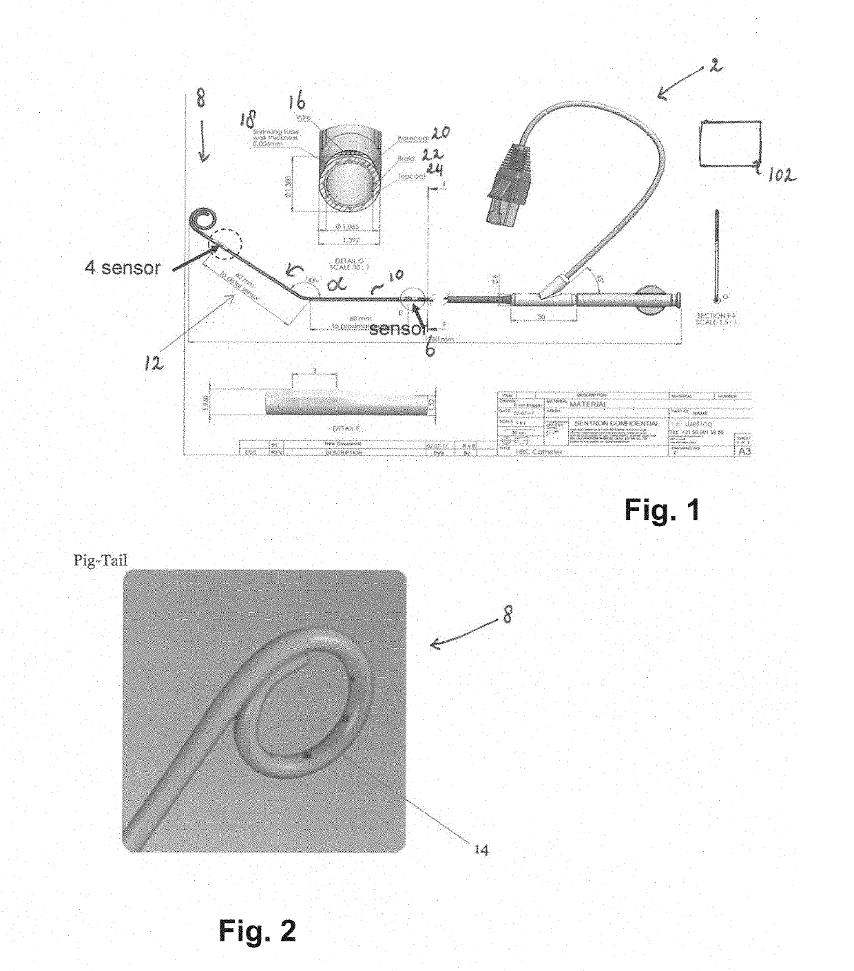
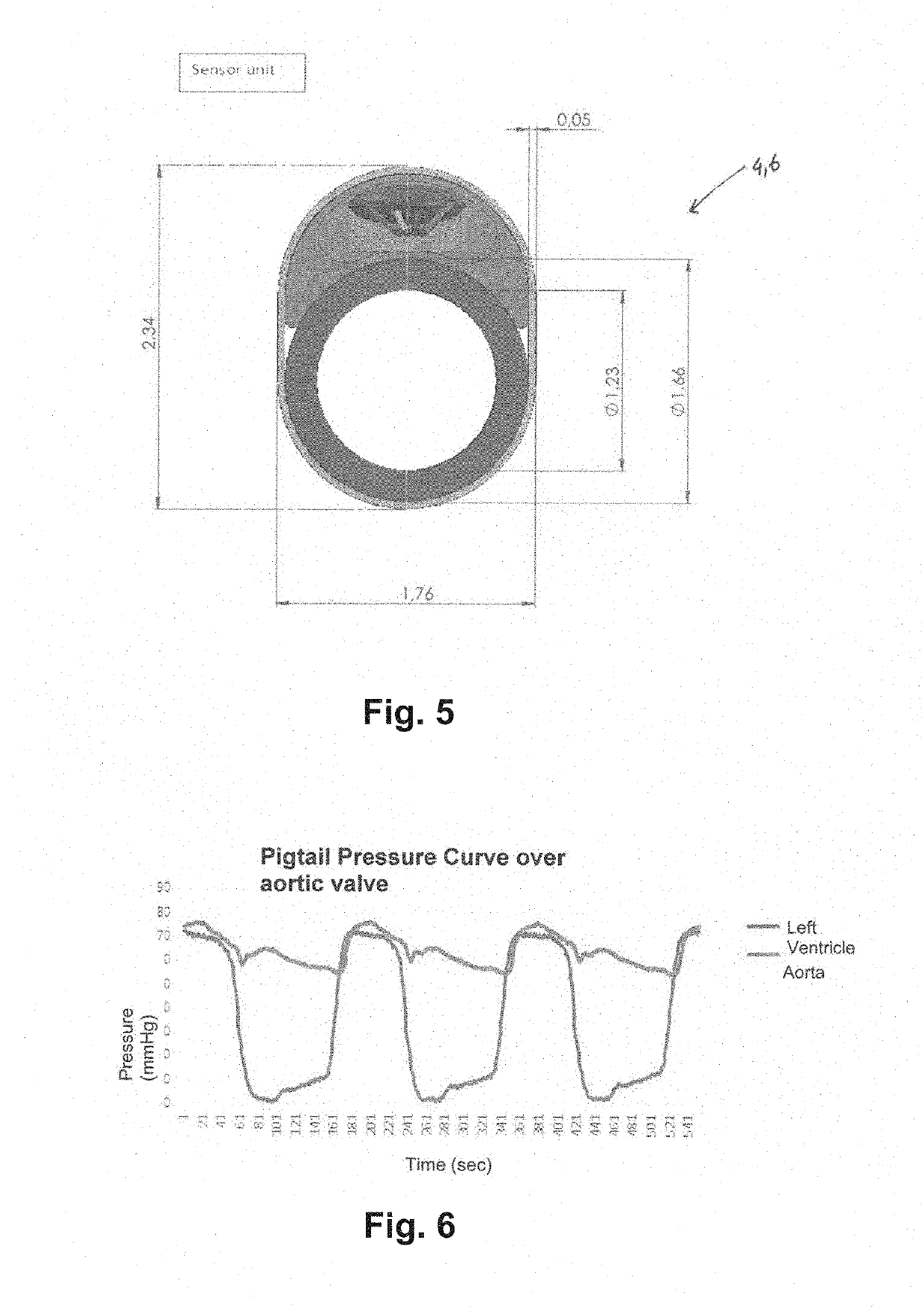
The present invention relates to a flexible catheter for the diagnosis and treatment of stenotic conditions in the circulatory system, particularly aortic stenosis. The catheter has a distal tip design that reduces the risk for tissue damage when in tissue contact. It can provide a conduit for the delivery of contrast fluid while exposing the patient to x-ray radiation under fluoroscopic imaging while examining the full range of pathological conditions contributing to the patient discomfort or clinical problem. Additionally, the catheter has multiple sensors to provide high-resolution pressure information with respect to two locations, proximal and respectively distal to a stenotic segment. The system and means disclosed by this invention provide accurate and high-resolution time-resolved as well as spatially resolved acquisition of multiple in-situ blood pressure measurements in a patient's vascular and cardiac system. The catheter is designed to withstand high-pressure contrast injection and maintain its functionality during the injection process. It can simultaneously and synchronizedly measure pressure in at least two locations, and it is designed to minimize tissue damage and provide safe and effective treatment options for stenotic conditions.

Problems solved by technology

This pressure profile will furthermore result in back-flow of blood into the pulmonary veins with associated increase in pulmonary capillary wedge pressure, and can potentially lead to pulmonary congestion, with pathological formation of edema.

Method used


Image

  • Dual Pressure Sensor Aortic-Valve Catheter
  • Dual Pressure Sensor Aortic-Valve Catheter
  • Dual Pressure Sensor Aortic-Valve Catheter

Examples


embodiment 1

[0047]In Embodiment 1, the medical device having a construction of a minimum of two pressure sensor units, wherein the respective distal and proximal pressure sensors are spaced apart, placed on the exterior surface of a catheter body. The spacing is optimally configured to allow the measurement of a pressure gradient between the two pressure points that has minimal impact resulting from boundary flow conditions resulting from the geometry of the cardia and vascular system.

embodiment 2

[0048]In Embodiment 2, the medical device comprises a minimum of one axial lumen running the length of the catheter.

[0049]In Embodiment 3, the device of Embodiment 1 is optionally configured to provide an outflow track on the distal end of the catheter body through a single lumen, or through a multitude of lumina.

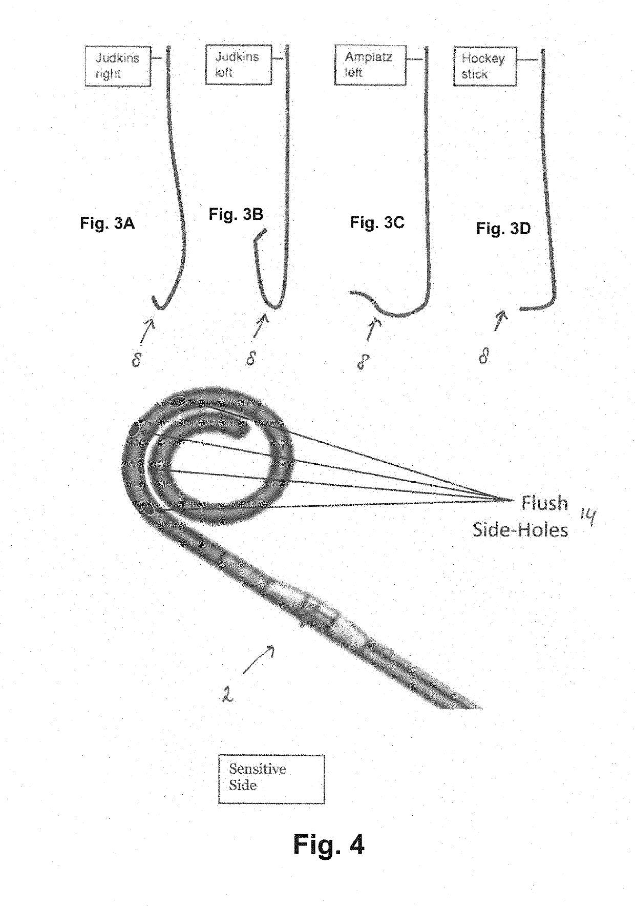
[0050]In Embodiment 4, the device of Embodiment 1, 2 and 3 is optionally configured in a preform shape, resembling a Amplatz, PigTail, J-shape, Hockeystick, or shape combinations with respective straight segments in preferred locations.

[0051]In Embodiment 5, the device of Embodiment 1-4, respectively, has one or more radiopaque markers identifying the respective locations of the distal tip of the catheter as well as the individual locations of the various pressure sensors.

[0052]In Embodiment 6, the device of Embodiment 1-4, respectively, has a braided or reinforced catheter wall that supports the infusion of various liquids through one of the lumina of the catheter from the...


PUM


Abstract

Disclosed is a system and method for in-situ and instantaneous measurement of a pressure gradient by means of real-time localized pressure measurement with two or more pressure sensors, operating under particular application with respect to blood pressure gradient across the aortic valve, or other heart valves, and associated regurgitation of blood flow due to leakage resulting from insufficient valve closure. The pressure gradient across a diseased valve can provide an indication for the clinical indication for therapeutic intervention, as well as performing quality control following prosthetic valve placement. The body can have a construction including at least one opening in communication with the fluid bed of the circulation of blood, connected by means of a fluid canal passing the length of the catheter in contact with the proximal exterior space for introduction of a guidewire, diagnostic fluid or other therapeutic or diagnostic catheter devices. The system includes a multi-sensor catheter, with sensors arranged along the length of the distal segment of the catheter body, spaced apart to provide simultaneous pressure measurement on either side of the respective valves of the heart, in addition to one or more lumina in the core of the catheter that will provide the means for introduction of diagnostic fluids which flow out through a multitude of holes in the body of the distal segment of the catheter body. Each respective pressure recording can be monitored synchronized with physiological effects, specifically cardiac contraction and electrocardiogram (ECG) events in high temporal resolution.

Description

CROSS-REFERENCE TO RELATED APPLICATION[0001]This application claims the benefit of U.S. Provisional Patent Application No. 62 / 633,944 filed Feb. 22, 2018, the disclosure of which is hereby incorporated by reference in its entirety.FIELD[0002]The present invention falls in the field of cardiac catheters, more specifically the field of minimally invasive diagnostic systems with respect to cardiac valve stenosis, next to vascular stenosis.BACKGROUND[0003]Aortic regurgitation is one of the consequences of aortic stenosis, in which, due to a pathological condition, the aortic valve becomes calcified, with associated stenosis, and as a result the valve will not open normally. The opening and closing of the aortic three-leaflet valve coincides with the contraction of the left ventricle, pushing blood out of the ventricle during systole, followed by relaxation of the heart muscle, causing the aortic valve to close due to the pressure resulting from the blood in the vascular system on the di...

Claims


Application Information

Patent Timeline
Patent Type & Authority Applications(United States)
IPC IPC(8): A61B5/0215A61B5/00
CPCA61B5/02158A61B5/6855A61B5/6857A61B5/6853A61B2562/0247A61B2562/043A61B5/0285A61B5/283
Inventor HARTHOLT, HENDRIKVAN DEN BROEK, RONALD ARTHUR
Owner WELLINQ HLDG BV
Learn More