Magnetic resonance imaging device and method for calculating oxygen extraction fractions
a magnetic resonance imaging and fractionation technology, applied in the field of magnetic resonance imaging (mri) technique, can solve the problem of long time of examination and achieve the effect of enhancing diagnostic accuracy
- Summary
- Abstract
- Description
- Claims
- Application Information
AI Technical Summary
Benefits of technology
Problems solved by technology
Method used
Image
Examples
first embodiment
[0052]In the present embodiment, a susceptibility distribution is calculated as the physical property, and the oxygen extraction fraction distribution is calculated from the susceptibility distribution. In the tissue separation process, the image of veins is separated from other tissues, and a venous distribution is calculated. With reference to a processing flowchart as shown in FIG. 4, there will now be described a processing of the present embodiment.
[0053][Measurement: S1001]
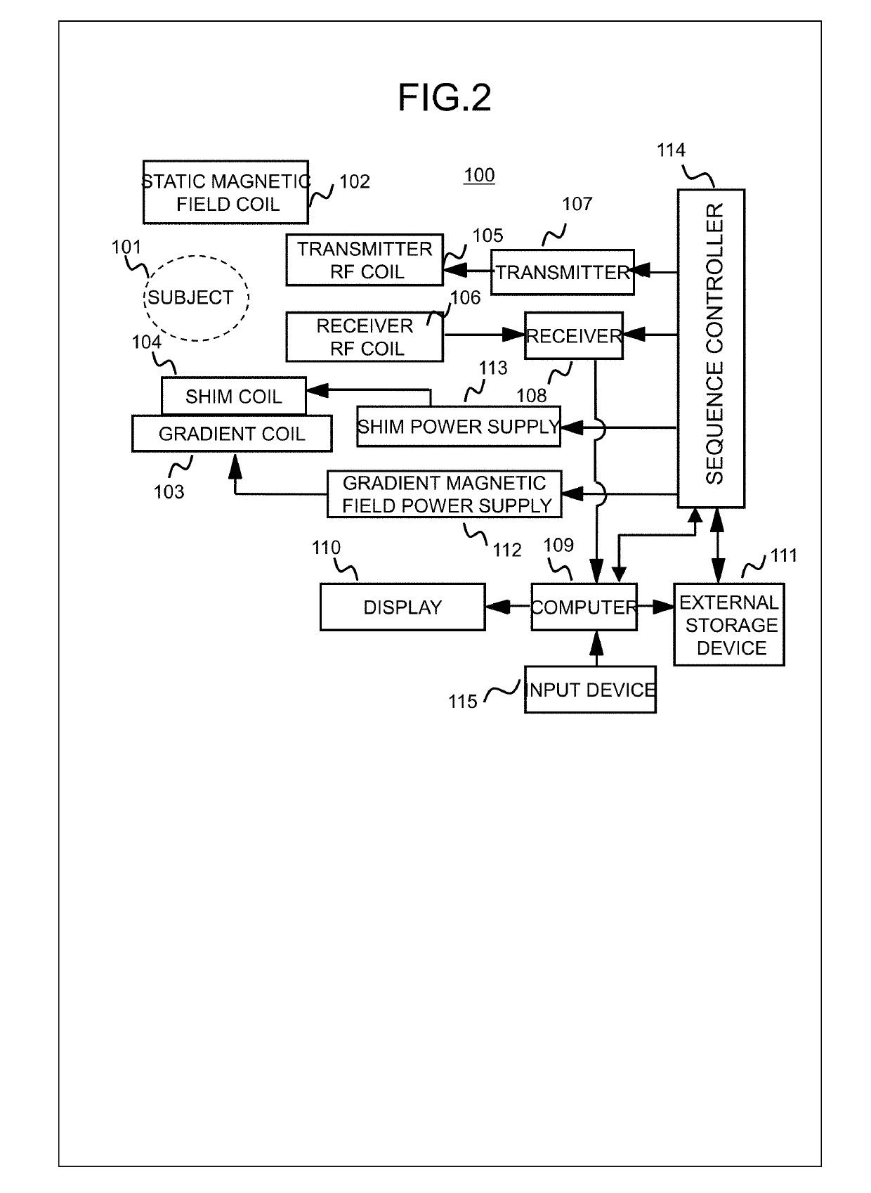
[0054]The measurement controller 310 operates the sequence controller 114, according to a pulse sequence that is configured based on parameters inputted by a user via the input device 115, and performs measurement for acquiring a nuclear magnetic resonance signal (echo signal) at a predetermined echo time (TE). The sequence controller 114 controls the measuring unit and performs measurement, in response to an instruction from the measurement controller 310. In the present embodiment, an echo signal at any se...
second embodiment
[0101]In the first embodiment, an example has been described where the susceptibility distribution is used as the physical property that reflects the oxygen extraction fraction. In the present embodiment, as the physical property distribution reflecting the oxygen extraction fraction, a distribution of apparent transverse relaxation rate (R2*) is calculated.
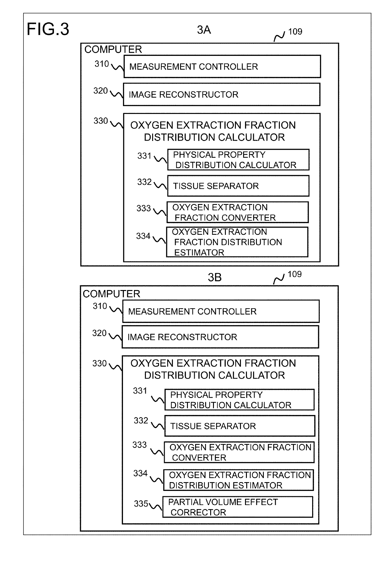
[0102]Also in the present embodiment, the configurations of the computer 109 and of the oxygen extraction fraction calculator 330 are the same as the first embodiment. However, the measurement controller 310 performs control for measuring echoes at a plurality of echo times, at least two, and for acquiring a plurality of complex images at different echo times. Processing details of the physical property distribution calculator 331 and of the oxygen extraction fraction converter 333 are different. Specifically, the physical property distribution calculator 331 calculates the distribution of R2* from the complex images obtained at ...
third embodiment
[0123]In the present embodiment, similar to the second embodiment, the physical property distribution calculator 331 calculate the apparent transverse relaxation rate R2* as a characteristic reflecting the oxygen extraction fraction. However, the processing performed by the tissue separator 332 (FIG. 3) is different from the second embodiment, and in the present embodiment, the apparent transverse relaxation rate R2* is separated into R2* of brain parenchyma and R2* of the other tissues.
[0124]There will now be described the processing of the oxygen extraction fraction distribution calculator 330 of the present embodiment, focusing on the points different from the second embodiment. FIG. 11 is a flowchart showing the processing of the present embodiment. In FIG. 11, the steps with identical details are labeled with the same reference numbers as the steps in FIG. 9, and detailed descriptions will not be provided redundantly.
[0125][Calculate R2* Distribution (R′ Distribution): S1101]
[0...
PUM
 Abstract
Description
Claims
Application Information
 - R&D
- Intellectual Property
- Life Sciences
- Materials
- Tech Scout
- Unparalleled Data Quality
- Higher Quality Content
- 60% Fewer Hallucinations
Browse by: Latest US Patents, China's latest patents, Technical Efficacy Thesaurus, Application Domain, Technology Topic, Popular Technical Reports.
© 2025 PatSnap. All rights reserved.Legal|Privacy policy|Modern Slavery Act Transparency Statement|Sitemap|About US| Contact US: help@patsnap.com


