Method of manufacturing emitter

a manufacturing method and technology of emitters, applied in the manufacture of electrode systems, electric discharge tubes/lamps, discharge tube coatings, etc., can solve the problems of degrading processing precision, difficult to form the tip in a pyramid shape, and difficult to perform a process

Active Publication Date: 2019-08-29
HITACHI HIGH TECH SCI CORP
View PDF0 Cites 3 Cited by
  • Summary
  • Abstract
  • Description
  • Claims
  • Application Information

AI Technical Summary

Benefits of technology

[0022]According to the present invention, it is possible to provide a method of manufacturing an emitter in w...

Problems solved by technology

However, there are some emitter materials in which it is difficult to form the tip in a pyramid shape through the electrolytic polishing.
There is a likelihood that this trace may degrade the precision of processing when the distal tip of the emitter material is sharpened to an atomic level, and also there is a likelihood of making it difficul...

Method used


Image

  • Method of manufacturing emitter
  • Method of manufacturing emitter
  • Method of manufacturing emitter

Examples


embodiment

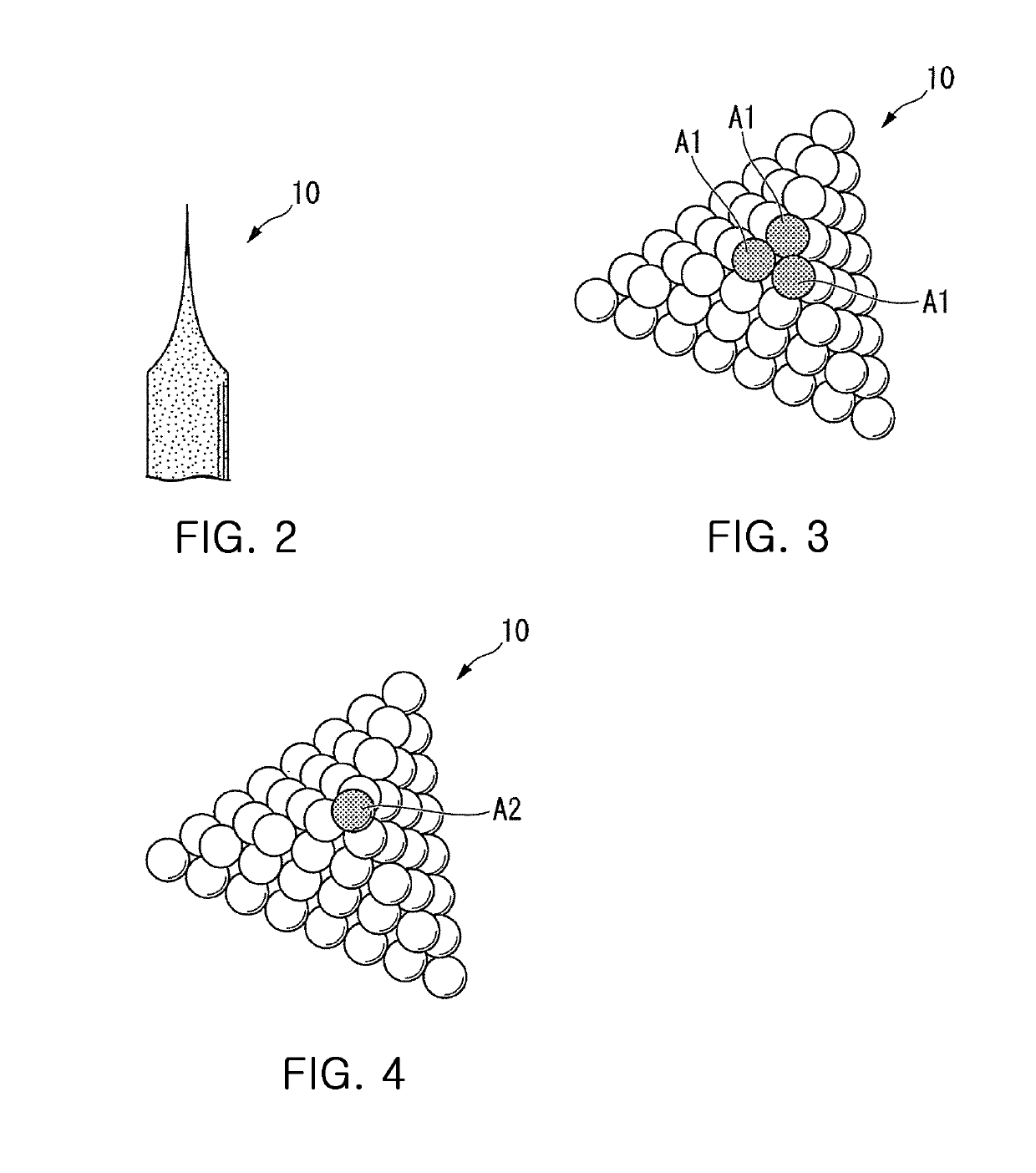
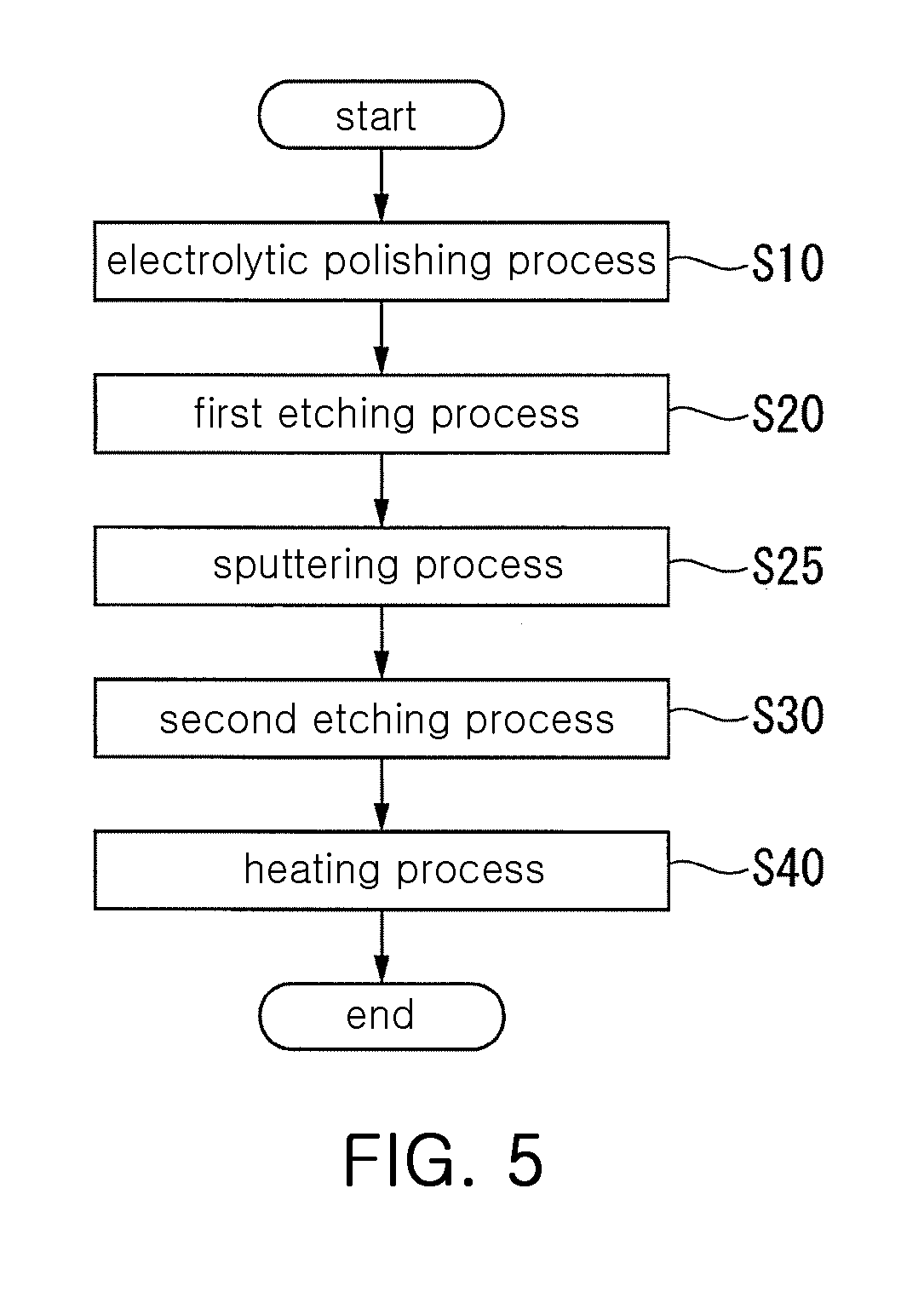
[0040]Hereinafter, an embodiment of the present invention will be described with reference to the drawings. Further, according to an embodiment, an emitter constituting a gas field ion source (GFIS) and used as an emission source of ion beam is described as an example.

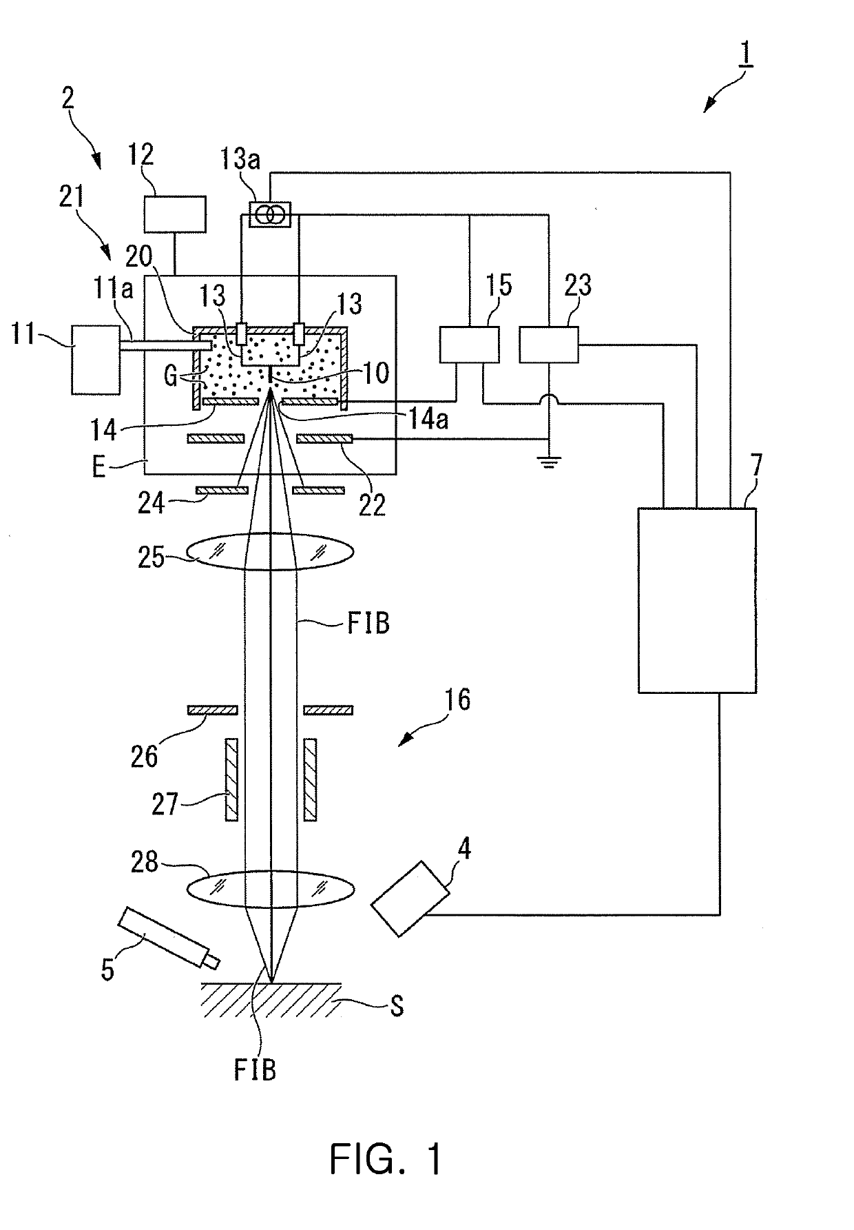
[0041]First, with reference to FIG. 1, a configuration of a focused ion beam apparatus having a focused ion beam column having the gas field ion source will be described. The focused ion beam apparatus 1 shown in FIG. 1 is an example of a focused ion beam apparatus having the focused ion beam column having the gas field ion source.

[0042]

[0043]As shown in FIG. 1, the focused ion beam apparatus 1 includes a focused ion beam column 2 for irradiating a sample S placed on a stage (not shown) with a focused ion beam FIB, a detector 4 for detecting secondary charged particles generated by emitting the focused ion beam FIB, a gas gun 5 for supplying a source gas used to form a deposition film, and a control unit 7 for displayi...


PUM

PropertyMeasurementUnit
Angleaaaaaaaaaa
Diameteraaaaaaaaaa
Sizeaaaaaaaaaa

Abstract

Disclosed is a method of manufacturing an emitter in which the tip of the emitter can be formed into a desired shape even when various materials are used for the emitter. The method includes performing an electrolytic polishing process of polishing a front end of a conductive emitter material so that a diameter of the front end is gradually reduced toward a tip; performing a first etching process by irradiating a processing portion of the emitter material processed by the electrolytic polishing process with a charged particle beam; performing a sputtering process by irradiating the pointed portion formed by the first etching process with a focused ion beam; and performing a secondary etching process of further sharpening the tip by an electric field induced gas etching processing while observing a crystal structure of the tip of the pointed portion processed by the sputtering process using a field ion microscope.

Description

CROSS REFERENCE TO RELATED APPLICATION(S)[0001]This application claims the benefit of Japan Patent Application No. JP 2018-030577 filed Feb. 23, 2018, which is hereby incorporated by reference in its entirety into this application.BACKGROUND OF THE INVENTION1. Technical Field[0002]The present invention relates to a method of manufacturing an emitter used as an emission source that emits electrons, ions, and the like.2. Description of the Related Art[0003]In the related art, a focused ion beam apparatus has an ion source for generating ions, and emits a focused ion beam in which ions generated from the ion source are focused. For example, a focused ion beam apparatus having a field ionization type ion source as an ion source is known (see, for example, Patent Document 1).[0004]The field ionization type ion source includes an emitter whose tip is sharpened at an atomic level, a gas source for supplying gas such as nitrogen gas or helium gas to the periphery of the emitter, a cooling u...

Claims


Application Information

Patent Timeline
IPC IPC(8): H01J9/02
CPCH01J2209/012H01J9/025H01J1/3042C25F3/00C25F3/08C25F3/16C25F3/26H01J37/3053
Inventor NAKAJIMA, YOKOKAWANAMI, YOSHIMIMORITANI, HIRONORIOBA, HIROSHI
Owner HITACHI HIGH TECH SCI CORP
Why Eureka
Try Eureka