Liquid Crystal Composite, Liquid Crystal Element, and Associated Selectively Dimmable Device
a selective dimming and liquid crystal technology, applied in liquid crystal compositions, instruments, chemistry apparatuses and processes, etc., can solve the problems of difficult to achieve, windows that fail opaquely, and become opaque, and achieve low haze and higher voltage requirements
- Summary
- Abstract
- Description
- Claims
- Application Information
AI Technical Summary
Benefits of technology
Problems solved by technology
Method used
Image
Examples
example 1
Fabrication of LC-Based Dimmable Device Using Capillary Method
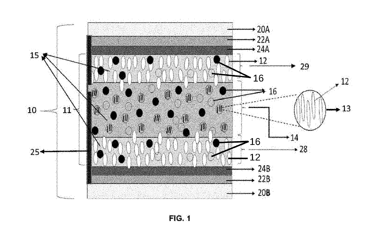
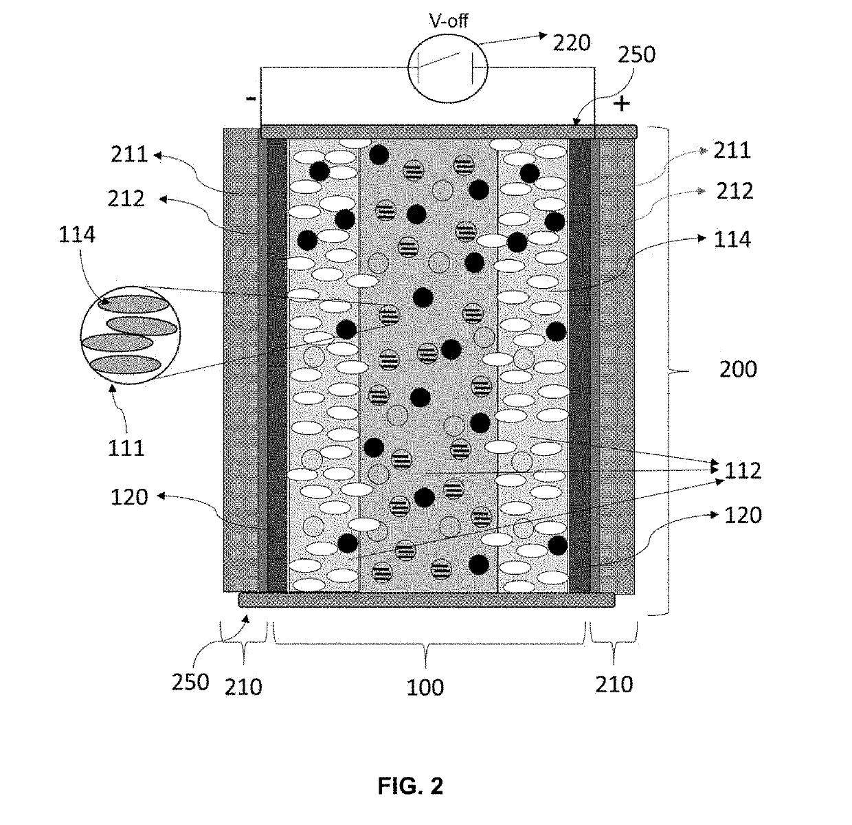
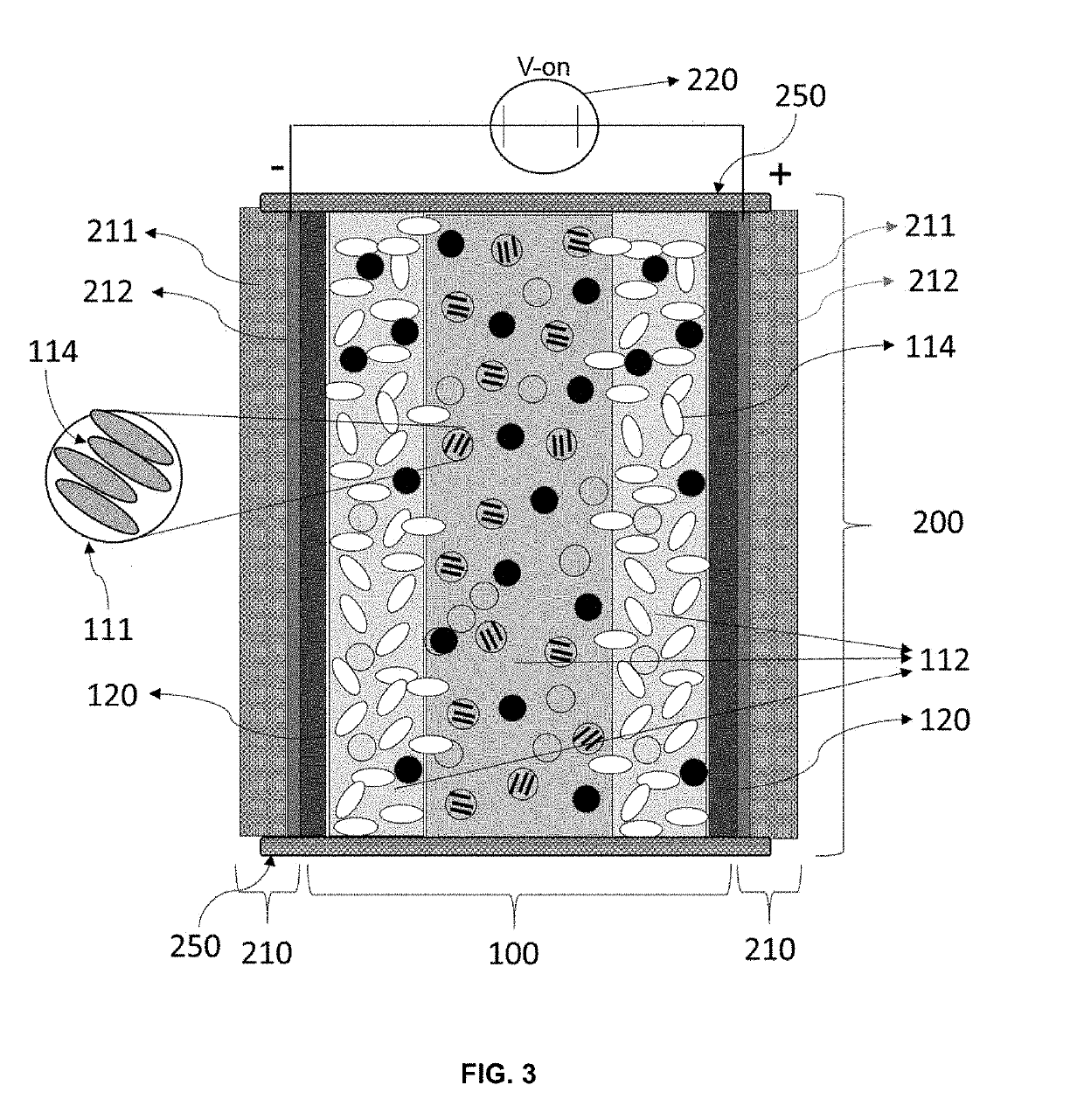
[0096]A selectively dimmable device based on a liquid crystal compound with negative dielectric anisotropy was fabricated using the capillary method. For the capillary method, a Homeotropic type liquid crystal test cell (KSHH-10 / B107M1NSS05, E.H.C Co. Ltd, Tokyo, Japan) was used for making the device. The test cell comprised of two substrates with supports that defined an active alignment area in between the two substrates. The size of the glass / ITO substrate was 20 mm×25 mm with a sheet resistance about 100 Ω / sq and the active alignment area was about 10 mm×10 mm with a cell gap of 10 μm. The cell was procured pre-coated with a cetyltrimethyl-ammonium bromide (CTAB, Tokyo Chemical Industries, Tokyo, Japan) with a tilting angle of about 85 to about 90 degrees. Also, because of the geometry the cell included supports to ensure preservation of the cell gap, separate spacers were not required to be inserted into the cell bef...
example 2
Fabrication of LC-Based Dimmable Device Using Capillary Method: Comparative Example
[0102]A selectively dimmable device based on a liquid crystal compound with negative dielectric anisotropy was fabricated using the capillary method. A Homeotropic type liquid crystal test cell (KSHH-10 / B107M1NSS05, E.H.C Co. Ltd, Tokyo, Japan) was used for making the device. The test cell was comprised of two opposing glass / ITO substrates, with supports, that define an active alignment area located within gap created by the two opposing substrates. The glass / ITO substrate measure 20 mm×25 mm with a sheet resistance about 100 Ω / sq and the active alignment area was about 10 mm×10 mm and a cell gap of 10 μm. The test cell was pre-coated with a cetyltrimethyl-ammonium bromide (CTAB, Tokyo Chemical Industries, Tokyo, Japan) with a tilt angle about 90 degrees.
[0103]Prior to the incorporation of the liquid crystal composite, the test cell was baked at 120° C. for 30 min to remove any impurities or moisture ...
example 3.1
Measurement of Device Haze
[0108]The optical characteristics of the fabricated dimmable devices were characterized by measuring the light allowed to pass through each, with and without an electric field present. An electrical connection was achieved by connecting wires to each terminal of the voltage source and to the respective glass / ITO substrates on the device such that an electric field would be applied across the device when the voltage source was energized or a voltage applied, and then placed into the haze meter. For the measurement of haze, an automated haze measurement system was built in-house. A haze meter (NDH-7000; Nippon Denshoku, Tokyo, Japan) was used to measure the total transmittance (Tt), parallel transmittance (Tp) and diffuse transmittance (Td). AC voltage was supplied from a voltage supplier (HP 8116A, Pulse / Function Generator, Hewlett Packard, Calif., USA) and amplified by a bipolar operational power supply / amplifier (BOP-500M, KEPCO, NY, USA). Voltage was supp...
PUM
| Property | Measurement | Unit |
|---|---|---|
| Electric potential / voltage | aaaaa | aaaaa |
| Electric potential / voltage | aaaaa | aaaaa |
| Haze | aaaaa | aaaaa |
Abstract
Description
Claims
Application Information
 - R&D
- Intellectual Property
- Life Sciences
- Materials
- Tech Scout
- Unparalleled Data Quality
- Higher Quality Content
- 60% Fewer Hallucinations
Browse by: Latest US Patents, China's latest patents, Technical Efficacy Thesaurus, Application Domain, Technology Topic, Popular Technical Reports.
© 2025 PatSnap. All rights reserved.Legal|Privacy policy|Modern Slavery Act Transparency Statement|Sitemap|About US| Contact US: help@patsnap.com


