
High dynamic range analog front-end receiver for long range lidar

a lidar and analog front-end technology, applied in the field of remote sensing, can solve the problems of reducing the response time and reducing the capacitance of the junction, so as to prevent the saturation of the tia, improve the regulation of the input voltage of the tia, and reduce the effect of the response tim

Active Publication Date: 2019-09-26
ANALOG DEVICES INT UNLTD CO
View PDF0 Cites 0 Cited by
  • Summary
  • Abstract
  • Description
  • Claims
  • Application Information

AI Technical Summary

Benefits of technology

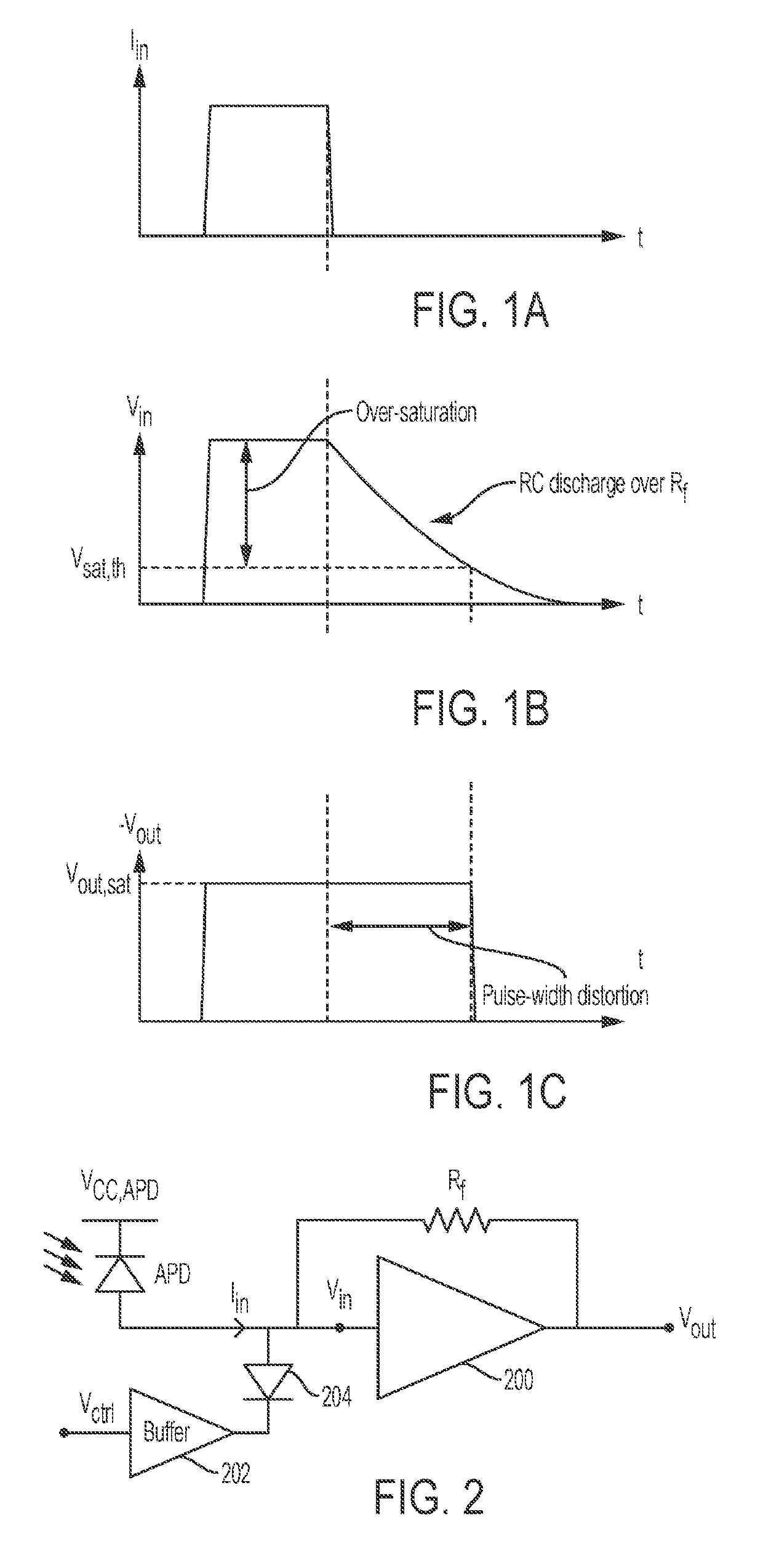
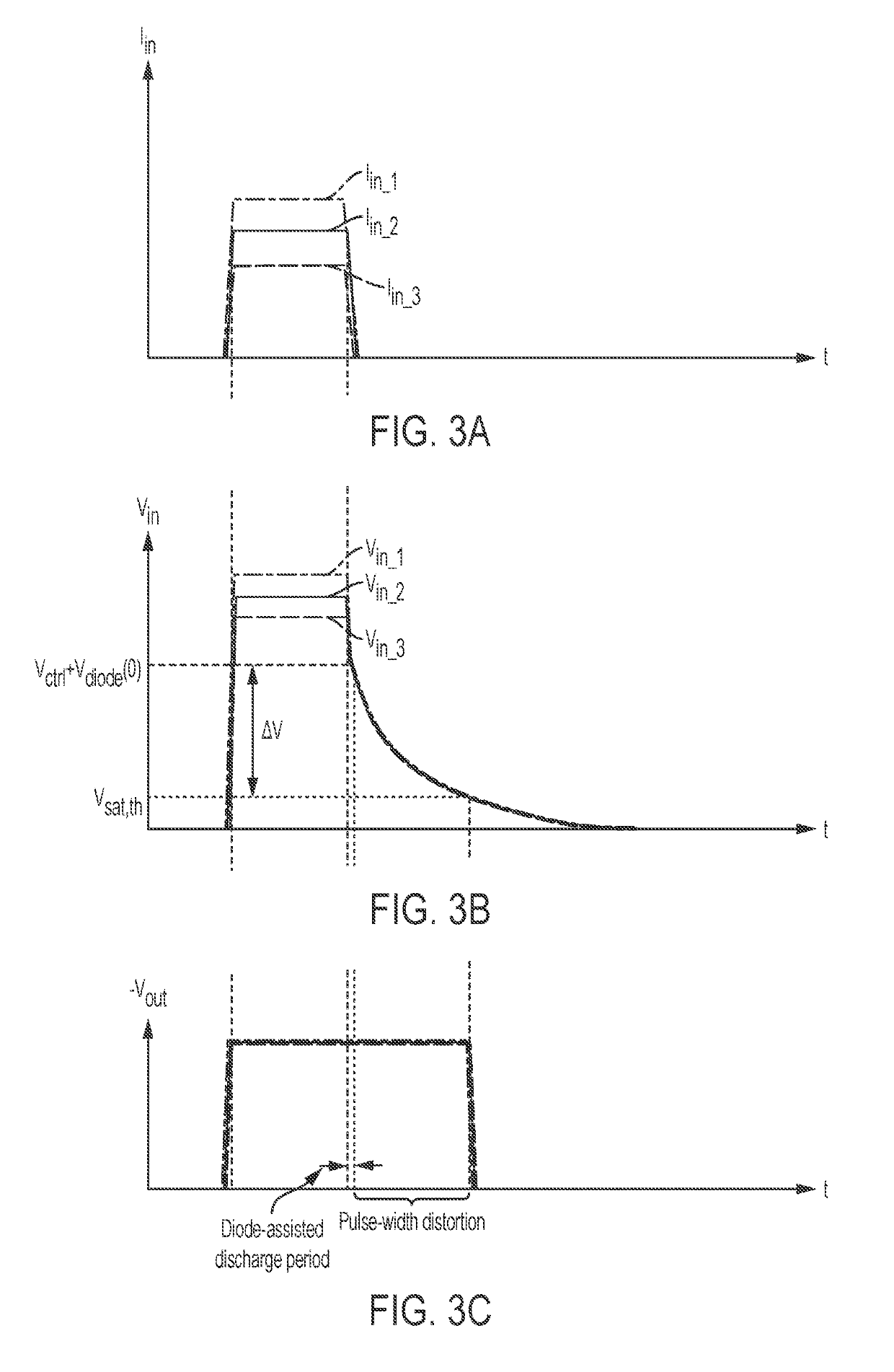
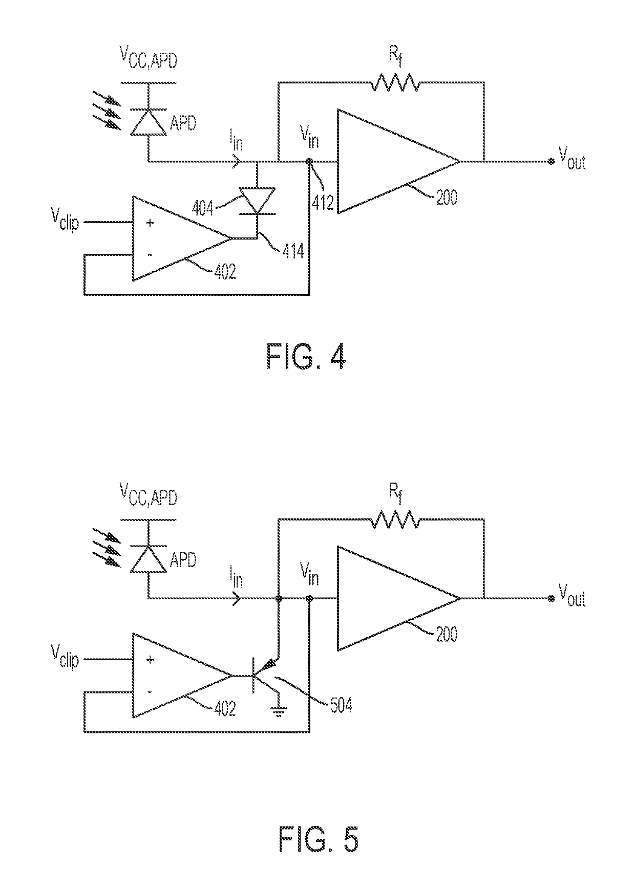
The patent text describes a system and method for operating a high dynamic range analog front-end receiver for long range LIDAR using a transimpedance amplifier (TIA). To prevent saturation of the TIA, a clipping circuit is used which regulates the input voltage of the TIA to stay close to its saturation threshold voltage. The clipping circuit can be connected in parallel with a second clipping circuit capable of dissipating higher input currents and thus higher voltages. A resistive element may be placed between the two clipping circuits to further limit the input current to the TIA. The front-end receiver with the TIA enables detection of the photocurrent from the receiving photodiode or APD with no or only minimal pulse-width distortion caused by large photocurrents. The technical effect of the invention is to provide a reliable and efficient analog front-end receiver for LIDAR that prevents saturation of the TIA and minimizes pulse-width distortion.

Problems solved by technology

This reduces the response time because the additional reverse bias increases the width of the depletion layer, which decreases the junction's capacitance.

Method used


Image

  • High dynamic range analog front-end receiver for long range lidar
  • High dynamic range analog front-end receiver for long range lidar
  • High dynamic range analog front-end receiver for long range lidar

Examples


Embodiment Construction

[0026]The pulsed time-of-flight (TOF) laser ranging method is based on the measurement of a transit time (ΔT) of a short laser pulse (width for example about 3 ns) to an optically visible target and back to the front-end receiver. The measured transit time can be converted to a distance (R) between the target and the receiver.

[0027]LIDAR based on pulsed TOF measurements is particularly appealing in environmental perception systems where a high measurement speed (>1000 results / s) is needed, where the dynamics of the received echo can be very wide (>1:1000) and where an accurate distance measurement (<1 cm) is needed even with a single transmitted pulse to distances of up to tens of meters to non-cooperative targets. Examples of this kind are anti-collision systems and scanners in traffic applications. For example, in automotive applications the dynamic range may exceed 1:100,000. In the case of a mirror-like reflection or a reflection from a close object, a very high input signal may...


PUM


Abstract

A system and method for operating a high dynamic range analog front-end receiver for long range LIDAR with a transimpedance amplifier (TIA) include a clipping circuit to prevent saturation of the TIA. The output of the clipping circuit is connected via a diode or transistor to the input of the TIA and regulated such that the input voltage of the TIA remains close to or is only slightly above the saturation threshold voltage of the TIA. The regulation of the input voltage of the TIA can be improved by connecting a limiting resistor in series with the diode or transistor. A second clipping circuit capable of dissipating higher input currents and thus higher voltages may be connected in parallel with the first clipping circuit. A resistive element may be placed between the first and second clipping circuits to further limit the input current to the TIA.

Description

RELATED APPLICATIONS[0001]This application claims the benefit of U.S. Provisional Application Ser. No. 62 / 477,053 filed on Mar. 27, 2017, and of U.S. Provisional Application Ser. No. 62 / 483,315 filed on Apr. 7, 2017 and U.S. patent application Ser. No. 15 / 698,491 filed on Sep. 7, 2017. The US Provisional and Non-Provisional Applications are hereby incorporated by reference in their entirety.FIELD OF THE DISCLOSURE[0002]The present disclosure relates to the field of remote sensing that uses light from a pulsed light source to measure ranges or distances from objects. More particularly, the present disclosure relates to shunt-feedback transimpedance amplifiers of the type used in remote sensing applications.BACKGROUND[0003]Remote sensing using light pulses emitted for example by lasers and retroreflected by distant objects is sometimes also referred to as LIDAR (light detection and ranging). A LIDAR receiver, hereinafter also referred to as a front-end receiver, includes an optical re...

Claims


Application Information

Patent Timeline
Patent Type & Authority Applications(United States)
IPC IPC(8): G01S17/93H03F3/45H03F1/26H03F1/32H03F1/08G01S7/486G01S7/483H04B10/69H03F3/08G01S7/4861
CPCH03F1/08H03F3/45475H04B10/693G01S7/4868H03F1/26G01S7/483H03F2200/66G01S7/4861G01S17/93H03F1/32H03F3/08G01S7/486G01S17/08
Inventor EKEN, YALCIN ALPEROGUZ, ALP
Owner ANALOG DEVICES INT UNLTD CO
Learn More