Eureka AIR delivers breakthrough ideas for toughest innovation challenges, trusted by R&D personnel around the world.

Hot surface igniters for cooktops

Active Publication Date: 2019-10-03
SCP R&D LLC
View PDF0 Cites 2 Cited by
  • Summary
  • Abstract
  • Description
  • Claims
  • Application Information

AI Technical Summary

Benefits of technology

This patent relates to gas cooktops with burners that include hot surface igniters. The technical effect of the patent is to provide a safer and more efficient alternative to traditional spark igniters, which can cause damage to electronic components and lead to control board failures. Hot surface igniters offer a faster ignition time and can be more easily replaced when reached end of life. The patent describes different configurations and methods for protecting the hot surface igniter and ensuring its proper functioning.

Problems solved by technology

The contact between the hammer and crystal causes a deformation and a large potential difference.
This large potential difference pulse generates an electromotive force that can cause damage to the electronic components and lead to control board failures.
In addition, customers often complain that the audible clicking sound of spark igniters is annoying and the delay in gas ignition is frightening.
However, if installed in the location of conventional spark igniters, hot surface igniters can be vulnerable to breakage during manufacturing assembling, cleaning or other burner maintenance activities.
In addition, providing hot surface igniters that can achieve a desirable ignition temperature in a suitably short time has proven to be challenging.

Method used


Image

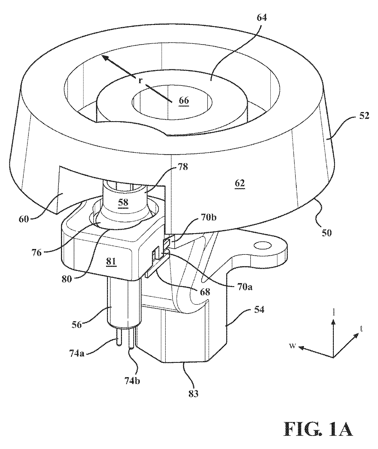
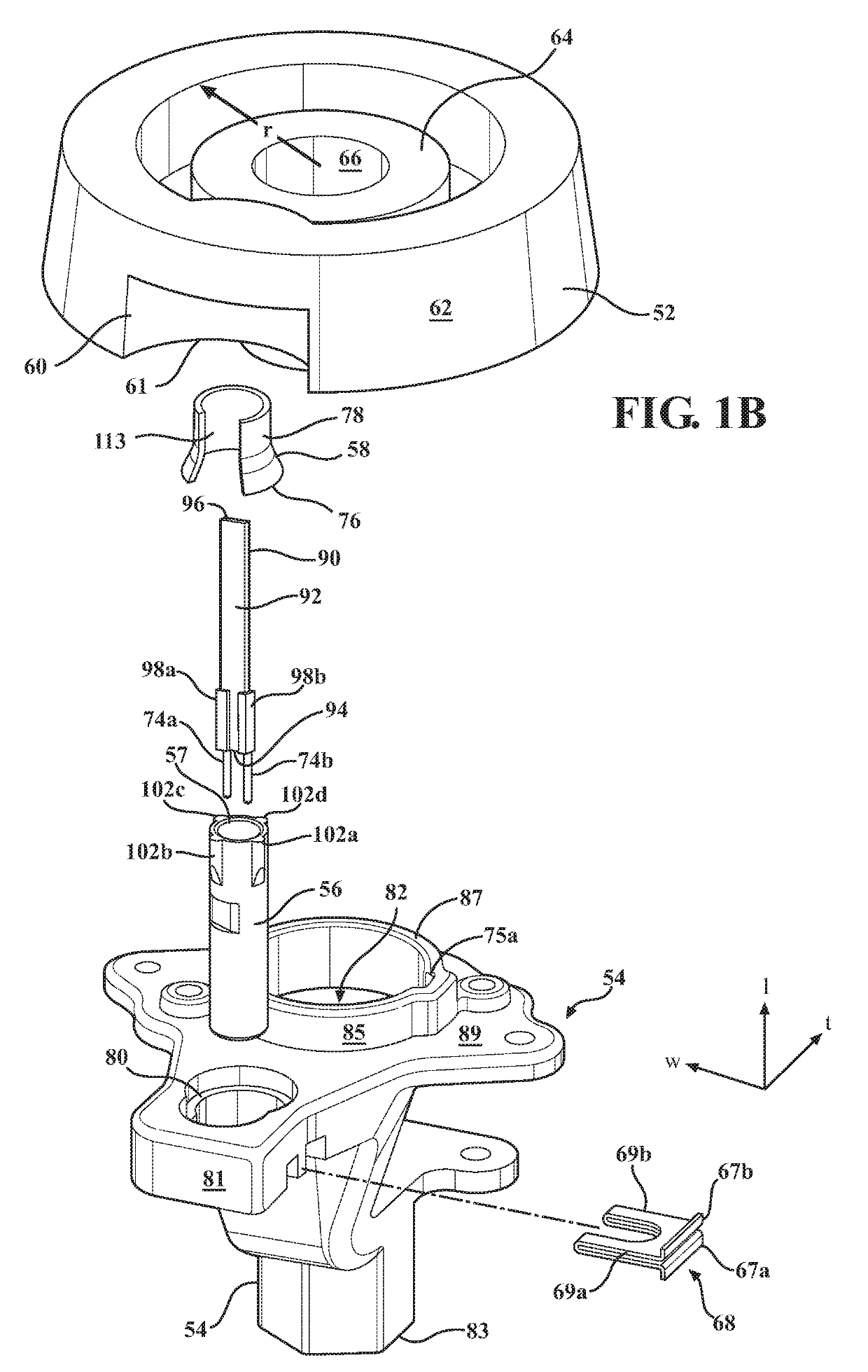
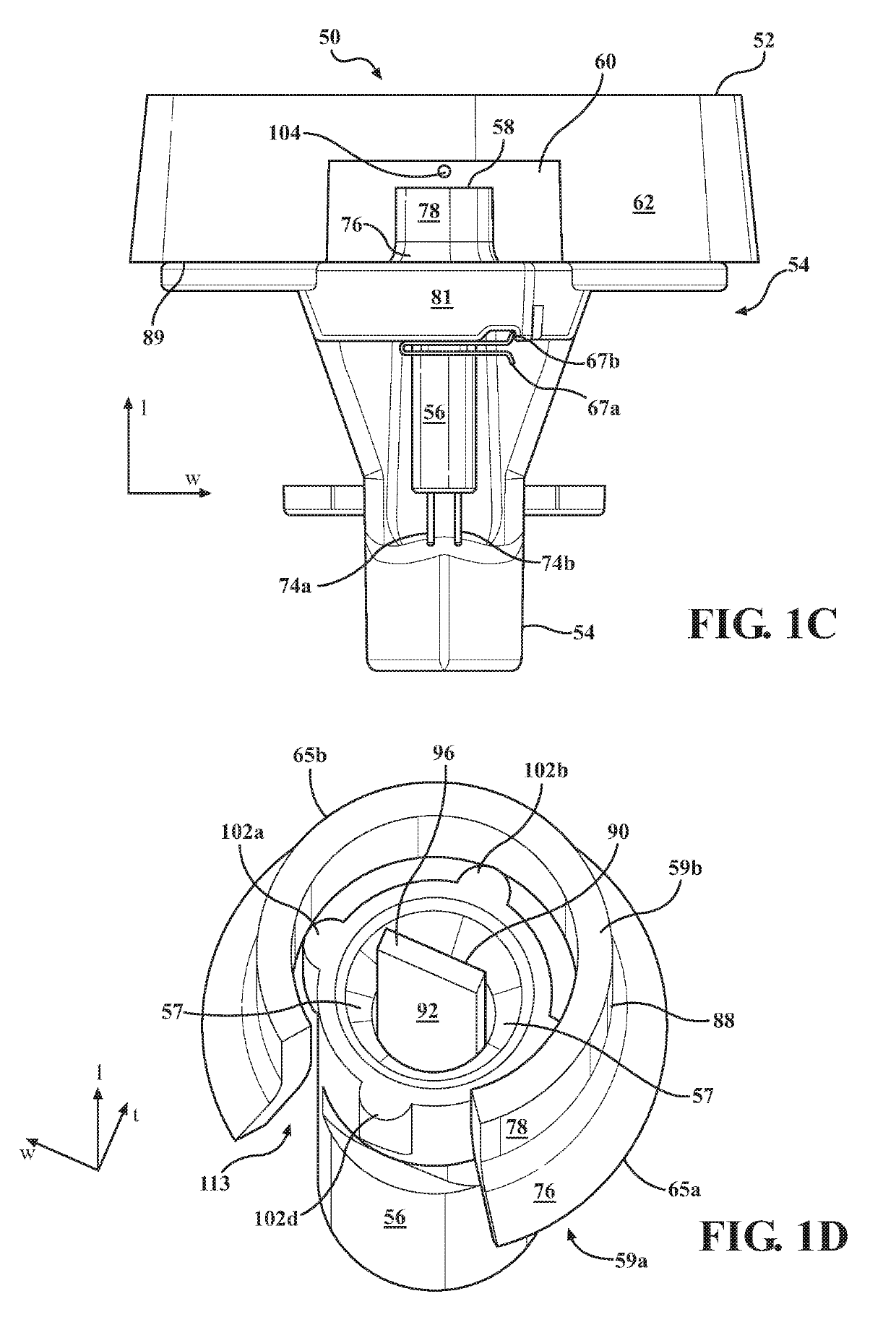
  • Hot surface igniters for cooktops
  • Hot surface igniters for cooktops
  • Hot surface igniters for cooktops

Examples


example

[0136]A hot surface igniter with the symmetric profile of FIG. 13A is provided. The igniter comprises two ceramic tiles 362 and 364 formed from silicon nitride, ytterbium oxide, and molybdenum disilicide. The amount of ytterbium oxide is from about 2 to about 15 percent by weight of the igniter body, and the amount of molybdenum disilicide is from about 3 to about 7 percent by weight. The balance of the tile ingredients comprises silicon nitride. The igniter is formed using the exemplary method of formation described above (e.g., powder processing, forming a powder compact, lamination, binder burn out, hot press sintering, dicing, brazing, and assembling).

[0137]A conductive ink pattern such as the pattern 340 depicted in FIG. 13C is screen printed on one of the tiles 362 and 364 and sandwiched there between. The conductive ink comprises from about 20 to about 30 percent tungsten carbide, from about 15 to about 40 percent silicon nitride, and from about 0.02 to about 5 percent ytterb...


PUM


Abstract

Hot surface igniter assemblies used in cooktops are shown and described. The hot surface igniters include a silicon nitride ceramic body with an embedded, resistive, heat-generating circuit. When energized, the circuit generates temperatures in excess of 2000° F. in under 4 seconds to ignite cooking gas such as natural gas. To prevent damage to the igniter during use or cleaning, an insulator assembly is provided which protects the distal end of the igniter ceramic body from damage while still exposing it to the cooking gas flow from the burner. In addition, a number of different terminal connection schemes for connecting the igniters to a power source are shown and described.

Description

CROSS-REFERENCE TO RELATED APPLICATIONS[0001]This application claims the benefit of U.S. Provisional Patent Application No. 62 / 648,574, filed on Mar. 27, 2018 and U.S. Provisional Patent Application No. 62 / 781,588, filed on Dec. 18, 2018, the entirety of each of which is hereby incorporated by reference.FIELD[0002]This disclosure relates to gas cooktops with burners that include hot surface igniter assemblies.BACKGROUND[0003]Gas cooktops include a set of burners, each of which receives and ignites cooking gas. The burner typically includes an orifice holder, which holds the orifice through which gas enters the burner, a crown, and a crown cap. The crown typically includes a plurality of flutes arranged around its circumference through which combusting gas is directed in a radially outward direction. Gas enters the crown via a central gas port in the crown. A crown cap sits atop the port to redirect gas flowing upward through the port through the flutes in a radially outward directio...

Claims


Application Information

Patent Timeline
IPC IPC(8): F24C3/10F23Q7/12F23N5/24
CPCF24C3/103F23Q7/12F23N5/24F23Q7/10F24C3/126H05B3/42F23Q7/22F23D2207/00F23N2227/42H05B2203/027H05B2203/013F23D14/06F24C3/085F24C15/108
Inventor SPROWL, BRUCE C.SHINDLE, JACK A.DAVIGNON, ROBERTDOUGHERTY, BRIAN C.BRAHMANDAM, SUDHIR
Owner SCP R&D LLC
Why Eureka
Eureka Blog
Learn More