Supercharge Your Innovation With Domain-Expert AI Agents!

Cavity-backed annular slot antenna array

a technology of annular slot antennas and cavity backs, which is applied in the direction of slot antennas, antenna details, antennas, etc., can solve the problems of cbas antennas with large antenna arrays, reducing the spacing limit, and limiting the geometry of cbas antennas. , to achieve the effect of sacrificing bandwidth or simplicity of antenna design, minimizing gain pattern variation, and optimizing antenna array space and performan

Active Publication Date: 2019-10-03
MITRE SPORTS INT LTD
View PDF0 Cites 6 Cited by
  • Summary
  • Abstract
  • Description
  • Claims
  • Application Information

AI Technical Summary

Benefits of technology

The patent text describes a new kind of antenna array that solves the problem of trading off bandwidth and inter-antenna element spacing in traditional applications. By using a compact and wideband design with minimal gain pattern variation and an inter-antenna element spacing less than a half wavelength without sacrificing bandwidth or simplicity of the antenna design, the antenna arrays can achieve a wide range of bandwidth. They also have low profile and can be flush-mounted to a metal surface, such as a vehicle. The antenna arrays include a unique design featuring slot apertures and magnetic current modes in a common backing cavity, which helps to minimize undesired modes and reduce inter-antenna element coupling. This design also allows for a wide range of applications, such as beamforming, nulling, and direction finding.

Problems solved by technology

However, traditional antenna arrays of CBAS antennas are limited by the geometry of the antennas.
This diameter is large enough to prevent the traditional CBAS antennas from being spaced equal to or less than half a wavelength apart in an array configuration, which results in larger antenna arrays of CBAS antennas and undesirable radiation in the form of grating lobes when beamforming.
Thus, traditional CBAS antenna arrays experience a tradeoff between bandwidth and inter-antenna element spacing, with hard lower limits on spacing.
Unlike the fin-type feed structures provided in the present disclosure, the traditional feed structures of the traditional CBAS antenna arrays cannot be placed in a common backing cavity as the traditional feed structures are not configured to prevent inter-antenna element coupling when the traditional feed structures are within a common backing cavity.
As such, the traditional CBAS antenna array space optimization is further limited by the traditional feed structure geometry.

Method used


Image

  • Cavity-backed annular slot antenna array
  • Cavity-backed annular slot antenna array
  • Cavity-backed annular slot antenna array

Examples


Embodiment Construction

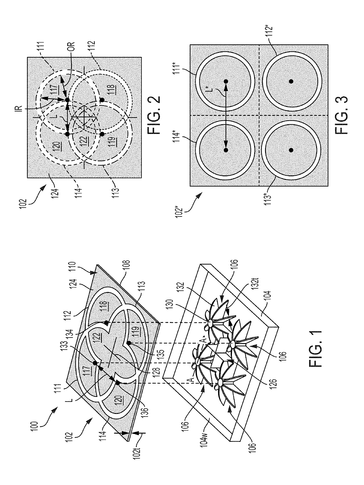
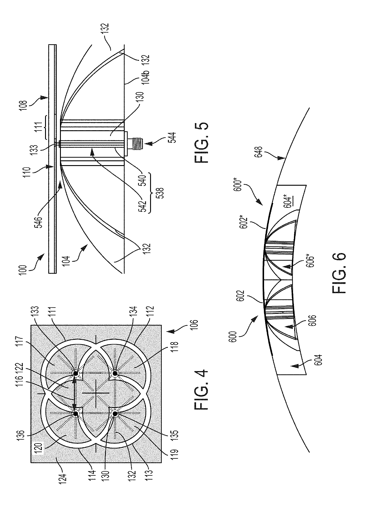
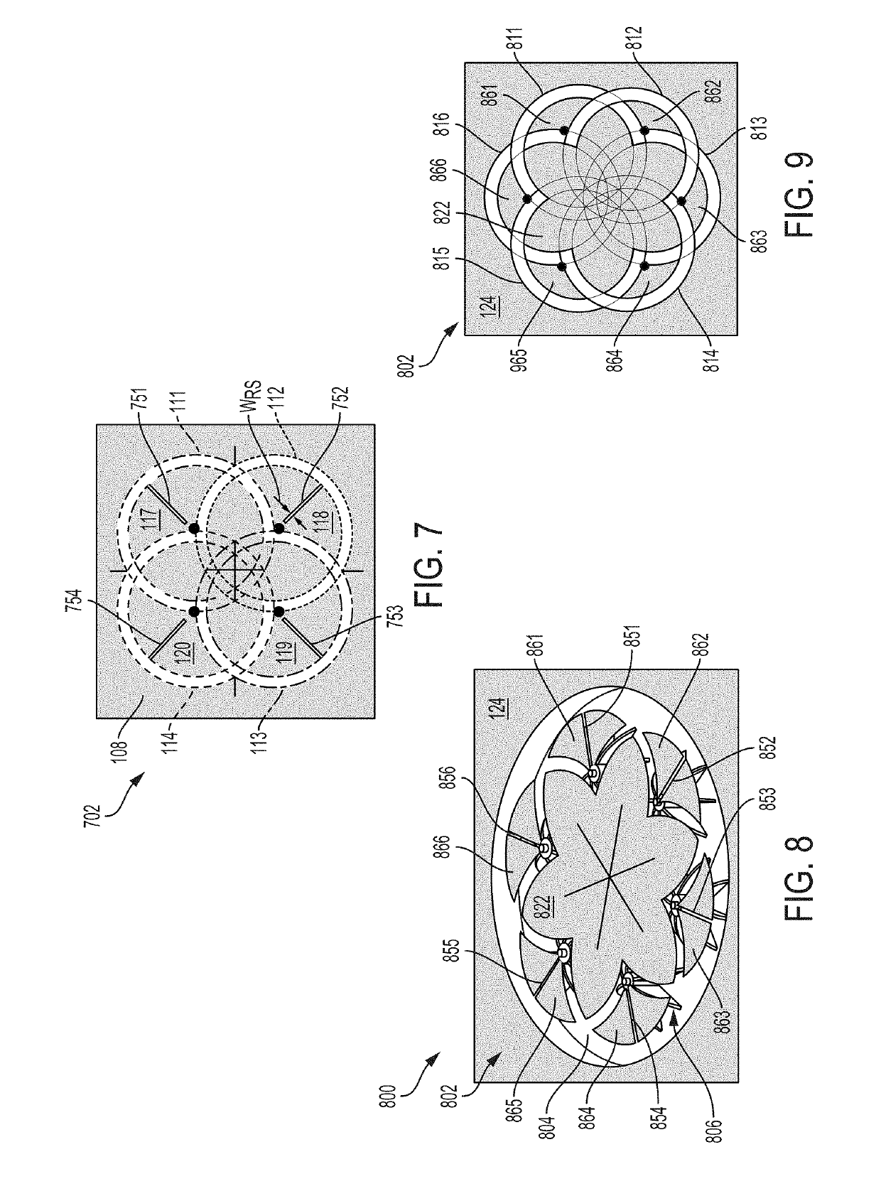
[0043]As discussed above, in CBAS antenna array applications, the optimization of antenna array space and performance are limited by the tradeoff between bandwidth and inter-antenna element spacing of the CBAS antenna arrays. The optimization of antenna array space is further limited by the geometry of the traditional feed structures in CBAS antenna arrays, as discussed above.

[0044]Disclosed herein are embodiments of compact and wideband CBAS antenna arrays having fin-type feed structures that help to overcome the limitations of the traditional CBAS antenna arrays and the traditional feed structures. The compact and wideband CBAS antenna arrays disclosed herein may have a minimal gain pattern variation and an inter-antenna element spacing less than a half wavelength. The CBAS antenna arrays provided in the present disclosure may achieve a bandwidth ranging from about 20% to about 35% of a center frequency of a matched operating frequency band of the antenna arrays. In some embodimen...


PUM


Abstract

Cavity backed slot antenna arrays for conformal antenna applications are provided. A cavity backed slot antenna array may include an aperture, first and second feed structures, and a backing cavity configured to support the aperture and the first and second feed structures. The aperture may have a dielectric layer and a metal layer disposed on the dielectric layer. The metal layer may have first and second annular regions. The first annular region may have a first slot region and the second annular region may have a second slot region, where the second slot region may partially overlap the first slot region. The metal layer may further include first and second radiating elements configured to radiate energy. Each of the first and second feed structures may include a central portion and a plurality of fin structures arranged radially around the central portion.

Description

STATEMENT REGARDING FEDERALLY SPONSORED RESEARCH OR DEVELOPMENT[0001]This invention was made with Government support under U.S. Government contract FA8702-17-C-0001 awarded by the U.S. Department of the Air Force. The Government has certain rights in this invention.FIELD OF THE INVENTION[0002]This invention relates generally to wide-band antennas and, more specifically, to cavity-backed overlapping annular slot antennas.BACKGROUND OF THE INVENTION[0003]A cavity-backed annular slot (CBAS) antenna typically includes a metal surface having a radiating element and an annular slot through which electromagnetic energy is radiated. The metal surface is backed by a resonant cavity that encloses an antenna feed structure for providing excitation to the radiating element. These CBAS antennas provide an omnidirectional azimuth gain pattern, which enables efficient reception and transmission between transmitters and receivers that are positioned in the same plane as the antenna.[0004]The struct...

Claims


Application Information

Patent Timeline
IPC IPC(8): H01Q13/18H01Q21/00H01Q13/10H01Q1/38
CPCH01Q13/18H01Q13/103H01Q21/0062H01Q1/38H01Q1/36H01Q1/523
Inventor ROBINSON, ERIC D.MCMICHAEL, IAN T.
Owner MITRE SPORTS INT LTD
Features
  • R&D
  • Intellectual Property
  • Life Sciences
  • Materials
  • Tech Scout
  • Unparalleled Data Quality
  • Higher Quality Content
  • 60% Fewer Hallucinations
Learn More