Naturally aspirated common rail diesel engine meeting ultra low pm emission by passive exhaust after treatment

Active Publication Date: 2019-11-14
MAHINDRA & MAHINDRA LTD
View PDF0 Cites 0 Cited by
  • Summary
  • Abstract
  • Description
  • Claims
  • Application Information

AI Technical Summary

Benefits of technology

[0009]A further object of the invention is to provide emission control systems which will optimize field fuel consumption with good drivability while concurrently minimizing emissions such as nitrous oxide and mini

Problems solved by technology

Since the catalysts employed also had a capability of promoting reduction reactions, there may have occurred during the treatment some reduction of nitrogen oxides into nitrogen and/or ammonia, although the presence of the latter gaseous stream in the products is undesirable.
This exhaust gas thus reintroduced in to the engine cylinder reduces the concentration of oxygen therein, which in turn lowers the maximum combustion temperature within the cylinder and slows the chemical reaction of the combustion process, decreasing

Method used


Image

  • Naturally aspirated common rail diesel engine meeting ultra low pm emission by passive exhaust after treatment
  • Naturally aspirated common rail diesel engine meeting ultra low pm emission by passive exhaust after treatment
  • Naturally aspirated common rail diesel engine meeting ultra low pm emission by passive exhaust after treatment

Examples


first embodiment

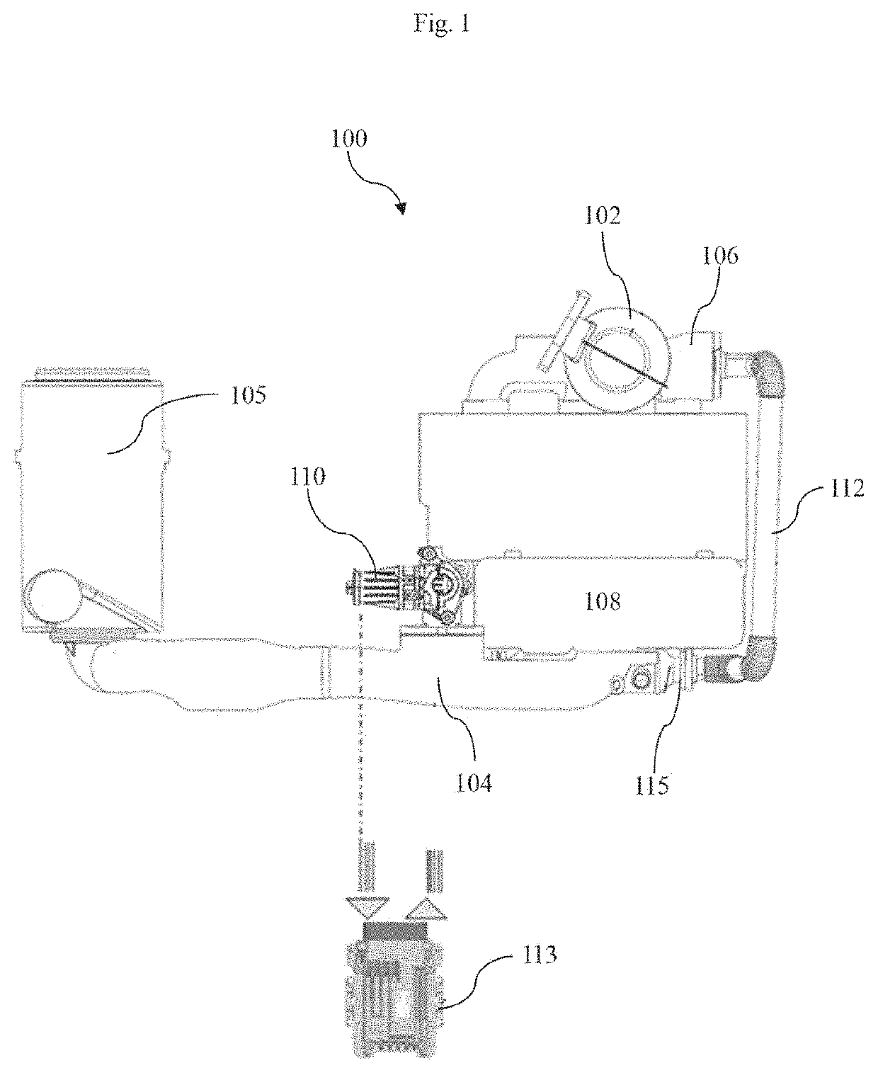
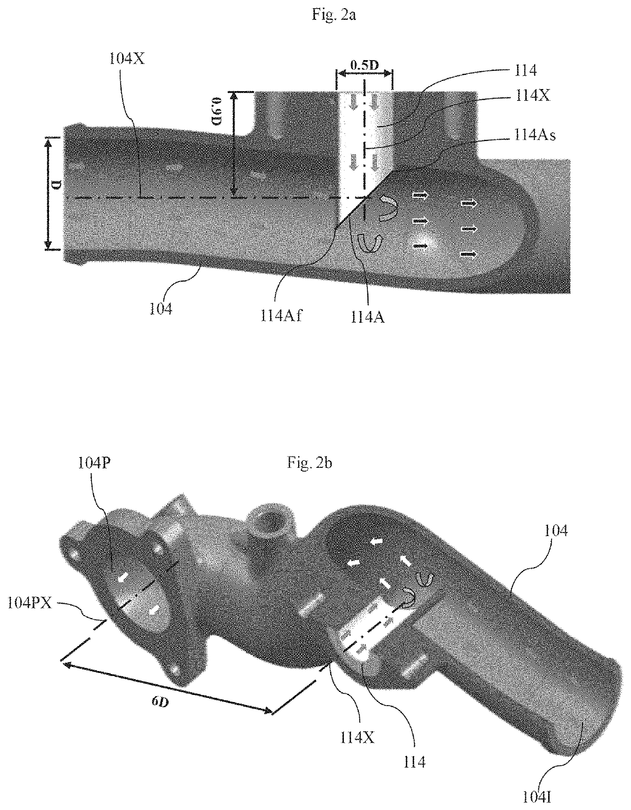
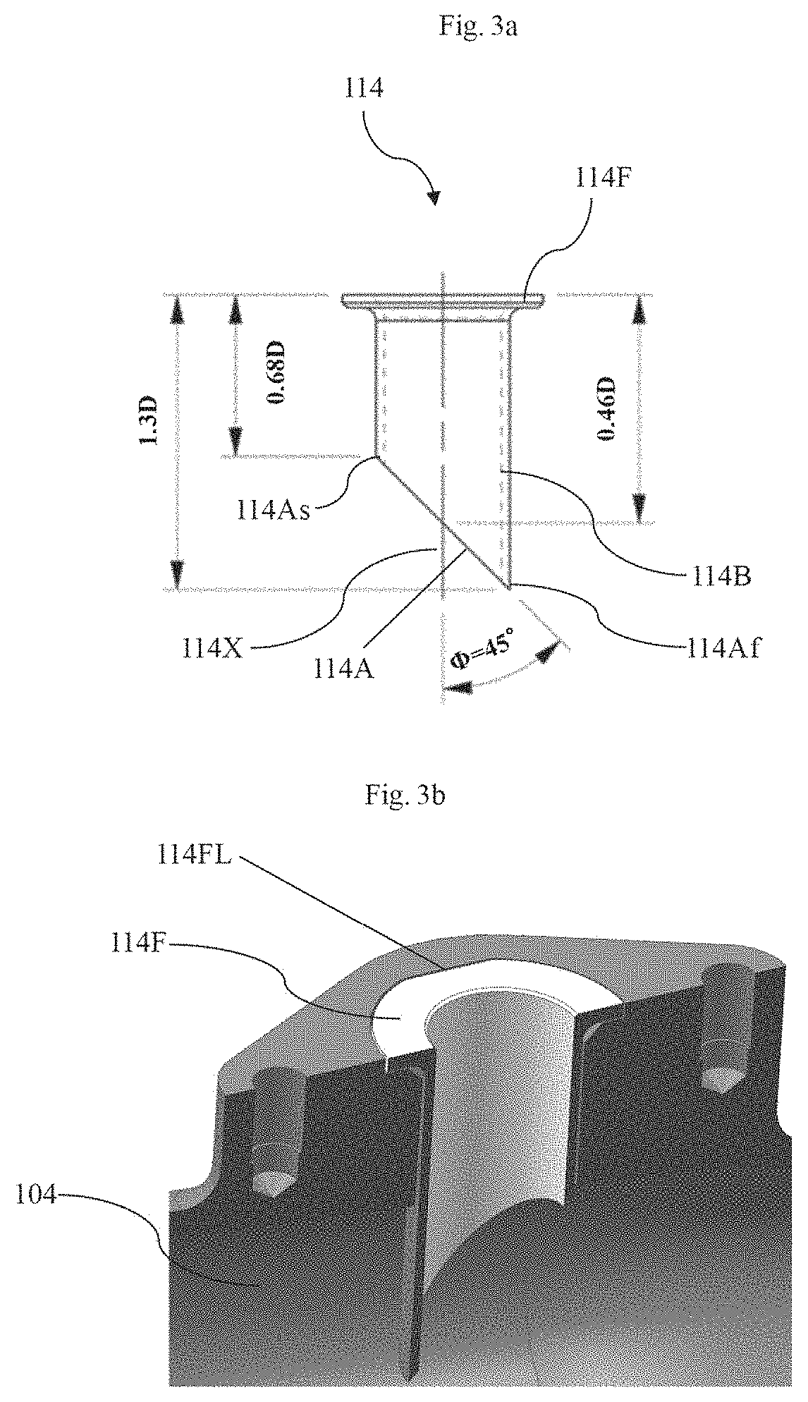
[0039]FIGS. 2a and 2b depict cross sectional views of an air intake conduit (104) and an exhaust gas mixing conduit (114) in assembled condition, as disclosed herein. The exhaust gas mixing conduit (114) receives exhaust gas from the exhaust gas recirculation cooler (115) through the exhaust gas recirculation valve (110). One end of the exhaust gas mixing conduit (114) is coupled to the exhaust gas recirculation valve (110) and the other end of the exhaust gas mixing conduit (114) is connected to the air intake conduit (104). The exhaust gas mixing conduit (114) is adapted to facilitate uniform mixing of exhaust gas with fresh air in the air intake conduit (104). For example, the exhaust gas mixing conduit (114) is adapted to introduce the exhaust gas at center of the air intake conduit (104) for uniform mixing of exhaust gas with fresh air in the air intake conduit (104). The exhaust gas mixing conduit (114) includes a body (114B) and a flange (114F). At least a portion of the bod...

second embodiment

[0052]In the second embodiment, the exhaust gas mixing conduit (214) includes an angular fluid outlet (214A, as shown in FIG. 6) adapted to dispense the mixed fluid from the exhaust gas mixing conduit (214) to the air intake conduit (204), where the angular fluid outlet (214A) is provided at the end of the body (214B), One end (214Af) of the angular exhaust gas outlet (214A) is disposed away from another end (214As) of the angular fluid outlet (214A). In an embodiment, the exhaust gas mixing conduit (214) is being cut at a predefined angle with respect to a central axis (214X, as shown in FIG. 6) of the exhaust gas mixing conduit (214) therein to form the angular fluid outlet (214A). For example, the exhaust gas mixing conduit (214) is being cut at 45 degree with respect to the central axis (214X) of the exhaust gas mixing conduit (214) therein to form the angular fluid outlet (214A). However, it is also within the scope of this invention to cut the exhaust gas mixing conduit (214) ...

third embodiment

[0063]In the third embodiment, the exhaust gas mixing conduit (314) is disposed concentrically onto the air intake venturi conduit (304), where a longitudinal axis of the exhaust gas mixing conduit (314) is coaxial to a longitudinal axis of the air intake venturi conduit (304). The exhaust gas mixing conduit (314) is a tubular member concentrically disposed onto the air intake venturi conduit (314). The exhaust gas mixing conduit (314) includes an exhaust gas inlet (3141, as shown in FIG. 10) adapted to facilitate entry of exhaust gas from the exhaust gas recirculation (EGR) valve (110) to the exhaust gas mixing conduit (314). The diameter of exhaust gas inlet (3141) of the exhaust gas mixing conduit (314) is half the inner diameter (D) of the air intake venturi conduit (314). It is also within the scope of this invention to provide the diameter of exhaust gas inlet (3141) of the exhaust gas mixing conduit (314) in any other number. An inner diameter of the exhaust gas mixing condui...


PUM

PropertyMeasurementUnit
Massaaaaaaaaaa
Molar densityaaaaaaaaaa
Currentaaaaaaaaaa

Abstract

Systems (100, 200 and 300) and methods (400, 500 and 600) for controlling exhaust gas emissions from naturally aspirated engine are disclosed. The system (100, 200 and 300) includes an open loop exhaust gas recirculation flow to the engine. The system (100, 200 and 300) includes a diesel oxidation catalyst (102, 202 and 302) mounted on or near exhaust manifold (106, 206 and 306) of the engine. Furthermore, the system (100 and 200) includes an exhaust gas mixing conduit (114 and 214) inserted into air intake conduit (104 and 204). The system (100, 200 and 300) further includes an exhaust gas recirculation valve (110, 210 and 310) mounted on cold side or a hot side of EGR cooler. Furthermore, the system (100, 210 and 310) includes an electronic control unit to control exhaust gas recirculation valve (110, 210 and 310) along with various other engine calibration parameters.

Description

CROSS REFERENCES TO RELATED APPLICATIONS[0001]The present application is a Continuation-In-Part of commonly assigned and co-pending U.S. application Ser. No. 14 / 907,234, filed on Jan. 22, 2016, which is a national stage filing under 35 U.S.C. § 371 of PCT Application Serial Number PCT / IN2014 / 000486, having an international filing date of Jul. 23, 2014, which claims foreign priority to Indian Application Serial Number 3271 / CHE / 2013, filed Jul. 23, 2013, entitled “Naturally Aspirated Common Rail Diesel Engine Meeting Ultra Low PM Emission by Passive Exhaust After Treatment”, the disclosures of which are hereby incorporated by reference in their entireties.FIELD OF INVENTION[0002]The embodiments herein relate to an emission control system for an internal combustion engine, and more particularly, to systems and methods for controlling exhaust gas emissions from a naturally aspirated engine, which minimizes nitrogen oxides (NOx) and other emissions while minimizing particulate matter emi...

Claims


Application Information

Patent Timeline
IPC IPC(8): F02M26/19F02D41/00B01D53/94F02M26/11F02M26/15F02M26/23B01F3/02B01F5/04B01F23/10
CPCB01D53/945B01D2255/1021F02M26/11F02M26/15F02M26/19F02M26/23F02D41/0077B01F3/02B01D2255/1023B01F5/0486F02D41/0065B01D53/944B01D53/9495B01F23/10B01F25/31242B01F25/3133B01F25/3143
Inventor R, VELUSAMYRAY, DIPANKARSADANAND, BHOSALEPRAVESH, HIRANANDANISANTOSH, RANER, SURESHATMARAM, DALVIS, DEEPAK
Owner MAHINDRA & MAHINDRA LTD
Why Eureka
Try Eureka