Heat flow management device and method for operating a heat flow management device

a technology of heat flow management and control device, which is applied in vehicle heating/cooling devices, battery/fuel cell control arrangements, transportation and packaging, etc., can solve the problems of reducing the capacity absorbed from ambient air, affecting reducing the efficiency of the entire heat pump system, so as to improve the performance and efficiency during heating operation. , the effect of simplifying the oil managemen

Active Publication Date: 2019-12-05
HANON SYST
View PDF0 Cites 40 Cited by
  • Summary
  • Abstract
  • Description
  • Claims
  • Application Information

AI Technical Summary

Benefits of technology

[0031]The second coolant circulation, for example a water-glycol mixture, includes several smaller circuits which can be connected with one another and separated from one another by means of 3 / 2-way valves. The primary function of this circuit is cooling electric power train components and / or batteries actively through refrigeration circuit cooling or passively through a heat exchanger disposed in the front end as a radiator. During heating operation this circuit is conceptualized for the heat absorption from the electric power train components. This previous power loss is subsequently transported to the chiller in order to provide evaporation heat. Absorbing and incorporating the power loss for the heating of the vehicle increases the performance and efficiency during heating operation.
[0032]All expansion elements can optionally also be completely closed such that these can also be employed as stop valves. Changing over between heating and cooling mode can here take place continuously without refrigerant compressor shutdown. A flow reversal in the ambient heat exchanger is not necessary in this system. This leads also to a simplified oil management, since oil traps in the system can be more easily avoided.

Problems solved by technology

Additionally, at cold ambient temperatures the heat absorption from the ambient air is limited in order to prevent the ambient heat exchanger from icing over.
Icing-over of the ambient heat exchanger impairs the heat transfer between air and refrigerant resulting in the reduction of the capacity absorbed from ambient air and consequently leads to the efficiency degradation of the entire heat pump system.
Due to the necessity of having to avoid the icing-over of the ambient heat exchanger, it is not possible at very low ambient temperatures to heat the vehicle cabin adequately if only ambient air is utilized as a heat source.
However, due to the multiplicity of the components conventionally required for such a system, the system complexity is increased and consequently also the system costs for each vehicle.
However, these systems entail the disadvantage of high energy consumption at simultaneously low blow-out temperatures of the air for heating the passenger cabin, especially in cold regions.
The electric auxiliary heater is not energy efficient and, beyond that, shortens the range of electric battery operated vehicles.
Heat pump systems, on the other hand, are complex due to the multiplicity of additional components, in such manner as heat exchanger, refrigerant valves and expansion elements.
This can possibly lead to an unintentional lowering or raising of the blast-out temperature of the air into the interior of the vehicle cabin when changing operating modes.

Method used


Image

  • Heat flow management device and method for operating a heat flow management device
  • Heat flow management device and method for operating a heat flow management device
  • Heat flow management device and method for operating a heat flow management device

Examples


Embodiment Construction

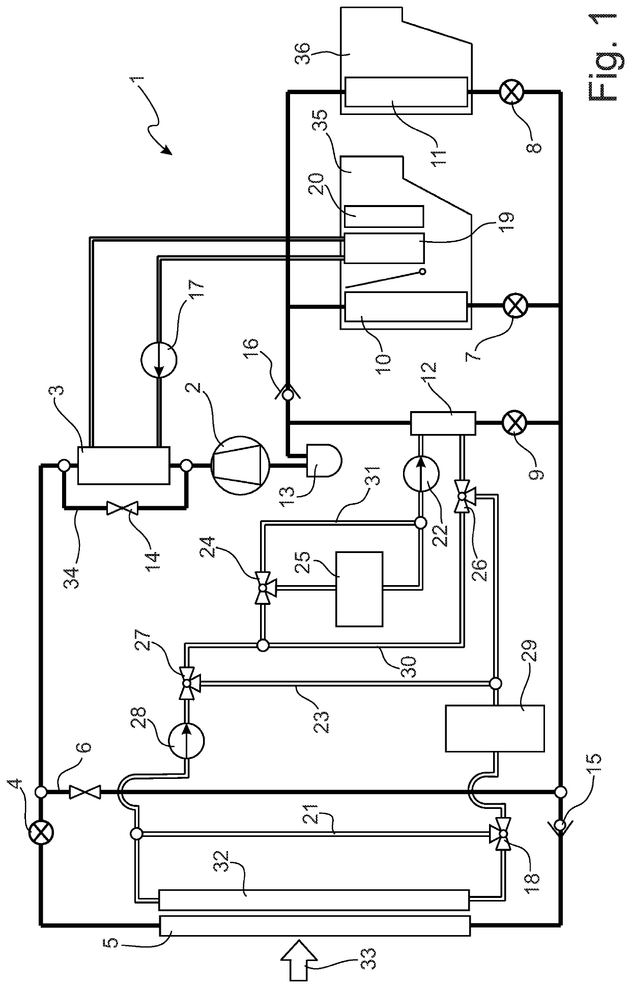
[0079]In FIG. 1 is shown the complete flow chart of the heat flow management device 1 with all circulations, subcirculations and device components. The heat flow management device 1 is substantially comprised of three circulations, thermally coupled with one another, however independently operable, wherein one circulation, in turn, can be divided into two subcirculations, each of which is operable independently and independent of the other.

[0080]The heat flow management device 1 comprises a refrigerant circulation that initially comprises the conventional basic components. These are in particular a compressor 2 as well as the ambient heat exchanger 5 as condenser / gas cooler as well as evaporators, the heat exchangers forward evaporator 10 and rearward evaporator 11, each with the associated expansion elements 7 and 8. As additional evaporator in the refrigerant circulation is provided a chiller 12 with the associated expansion element 9 for cooling the second circulation of the powe...


PUM


Abstract

Heat flow management device for motor vehicles has a refrigerant circulation, a power train coolant circulation and a heating line heat carrier circulation. The refrigerant circulation includes a compressor, an indirect condenser, an expansion element, an ambient heat exchanger, an evaporator and a chiller. The power train coolant circulation includes a coolant pump, the chiller, an electric motor heat exchanger and a power train coolant radiator, wherein the heating line heat carrier circulation comprises a coolant pump, the indirect condenser and a heating heat exchanger, wherein the refrigerant circulation and the power train coolant circulation are directly thermally coupled with one another across the chiller. Refrigerant circulation and heating line heat carrier circulation are directly thermally coupled with one another across the indirect condenser. Power train coolant circulation and the heating line heat carrier circulation are only indirectly thermally coupled with one another across the refrigerant circulation.

Description

FIELD OF THE INVENTION[0001]The invention relates to a heat flow management device as a component of a climate control system for high-efficiency motor vehicles with low exhaust or lost heat generation.BACKGROUND OF THE INVENTION[0002]The invention relates in particular to a heat flow management system for electric vehicles (EV), vehicles with hybrid drive (HEV), plug-in hybrids (PHEV) or fuel cell vehicles, which are at least partially driven electromotively and which are equipped with high-voltage batteries or accumulators.[0003]Prior art discloses that electric vehicles, vehicles with electric drive as well as also driven by internal combustion engine, so-called hybrids, fuel cell vehicles and high-efficiency vehicles driven by internal combustion engine do not generate sufficient exhaust or lost heat to heat the passenger compartment during the winter commensurate with the requirement of thermal comfort.[0004]A cost-effective and space-saving solution of this problem is an elect...

Claims


Application Information

Patent Timeline
Patent Type & Authority Applications(United States)
IPC IPC(8): B60H1/00B60H1/03B60H1/14B60H1/22B60H1/32
CPCB60H1/00885B60H2001/00942B60H1/3213B60H1/143B60H1/00021B60H2001/2287B60H2001/00128B60H2001/00961B60H1/2221B60H1/00485B60H1/00278B60H1/034B60H1/00907B60H2001/225B60H2001/00164B60H1/004B60H2001/00121B60H1/00735B60H1/03B60L58/26B60L58/27B60H1/00921B60H2001/00928B60H2001/00949B60H1/32284B60H2001/00307B60H1/00899B60H1/00385
Inventor DURRANI, NAVIDHÖTZEL, MARTINHAAS, TOBIAS
Owner HANON SYST
Why Eureka
Try Eureka