
Wireless communication apparatus with combined frequency and polarization diversity between transmitter and receiver channels

a communication apparatus and combined technology, applied in the field of millimeterwave communication apparatus, can solve the problems of reducing the size of the system, affecting the operation of the system, so as to reduce the loss of insertion

Inactive Publication Date: 2020-01-16
OBSHCHESTVO S OGRANICHENNOJ OTVETSTVENNOSTYU RADIO GIGABIT
View PDF9 Cites 4 Cited by
  • Summary
  • Abstract
  • Description
  • Claims
  • Application Information

AI Technical Summary

Benefits of technology

The invention provides a way to maintain a required isolation level between the transmitter and receiver with low insertion loss. This is achieved by using a high-isolation level that can be achieved either with standard waveguide-based filters or modern low-cost printed technologies. The invention also combines the isolation provided by cross-polarization of the antenna and filtering to simplify the filter requirements. Additionally, the invention allows for the reduction of filters needed and decreases the insertion loss level. The invention also includes the use of a common antenna for both transmitter and receiver units, reducing overall cost and simplifying assembly procedures. The Antenna of the invention provides high gain value and long operational distance for high throughput data transfer. The quality factors and orders of the filters are different to reduce insertion loss in the radio frequency chain.

Problems solved by technology

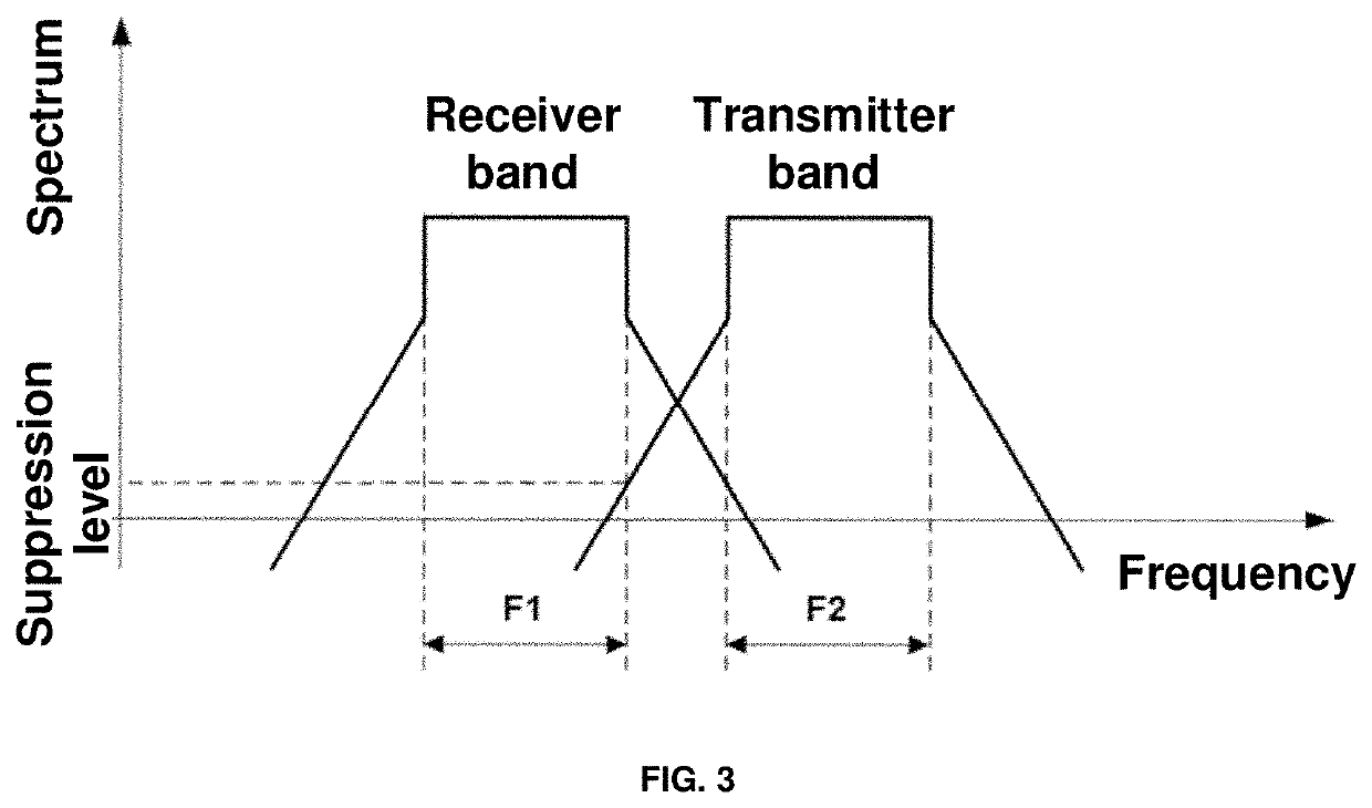
Generally, simultaneous transmission and reception of the signals from a common antenna are impossible in the same time slot and the same frequency band because in that case the low-power received signal will be strongly distorted by the high-power transmitted signal that is typically millions (and even billions) times stronger than the received one.
However, it is commonly inapplicable in practical communication systems since it leads to a significant increase of the system size and in some cases, requires separate realization of the transmitting and receiving devices.
This is especially inefficient for the communication applications where the narrow-beam antennas with high gain and correspondingly large aperture are typically implemented that is necessary to increase the operating distance.
Unfortunately, an isolation level in such a device is typically not sufficient for a pure diversity of the transmitting and receiving signals.
Utilization of such devices is often associated with the design complexity and an increase of the radio frequency circuit insertion loss that is especially critical for microwave and millimeter-wave applications.
Moreover, in the majority of the millimeter-wave communication systems diplexers and orthomode transducers are generally realized as separate waveguide modules that are typically bulky and expensive in manufacturing.
This significantly increases the overall material costs and provide additional expenses for manufacturing and assembling of the millimeter-wave communication system's transceivers.
Such filters regardless of the implementation method introduce additional losses in the microwave signal path.
On the other hand, such a filter is of considerable size and requires precise and expensive manufacturing technologies.
Moreover, the filter with the required suppression level typically cannot be realized on the planar substrate (to decrease the size and manufacturing costs) because in that case, the additional insertion loss will be around 5-10 dB or more, that is unacceptable.

Method used


Image

  • Wireless communication apparatus with combined frequency and polarization diversity between transmitter and receiver channels
  • Wireless communication apparatus with combined frequency and polarization diversity between transmitter and receiver channels
  • Wireless communication apparatus with combined frequency and polarization diversity between transmitter and receiver channels

Examples


Embodiment Construction

[0052]The present invention can be completely understood from the following description of some specific embodiments of the wireless communication apparatus with combined frequency and polarization diversity between the transmitter and receiver channels on the examples of the apparatus implementation in the millimeter-wave point-to-point communication systems with high data throughput.

[0053]The wireless communication apparatus according to the disclosed invention provides required isolation level between the transmitter and receiver with reduced insertion loss and also with less labor and resources expenses for manufacturing and assembling of the millimeter-wave transceiving device.

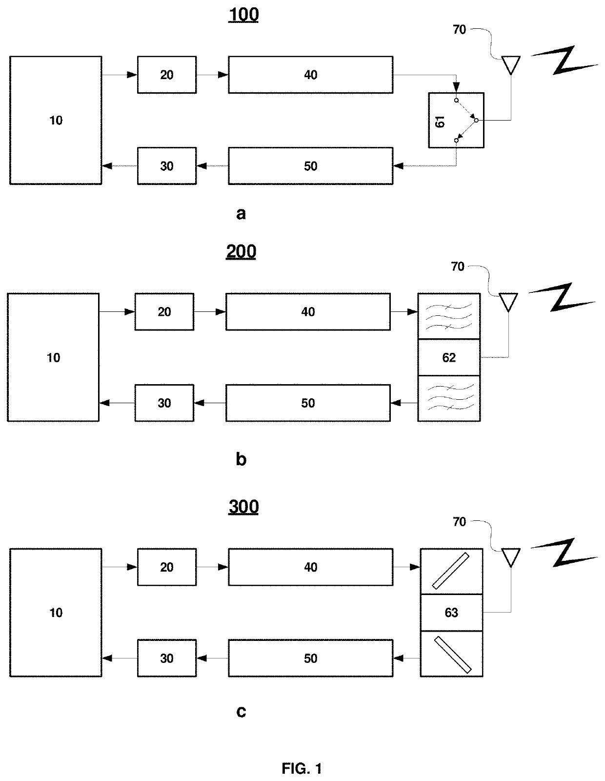
[0054]FIG. 1. shows block diagrams of the known from the background art communication apparatuses that implement various approaches for the diversity of the transmitted and the received signals. The device (100) that is shown in FIG. 1(a), uses the time-division diversity scheme (duplexing). It consists o...


PUM


Abstract

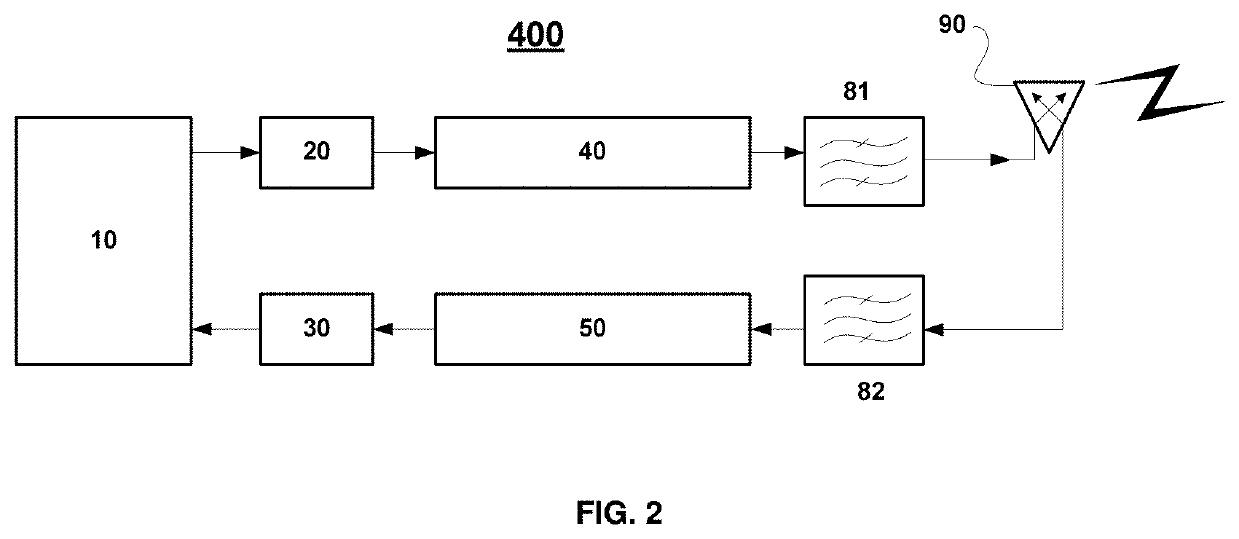
The invention relates to the field of wireless communication systems operating in a duplex mode for data transmission and reception and in particular to the millimeter-wave communication apparatus with high data throughput. The communication apparatus comprises a dual-polarized antenna with a corresponding first and second ports, optimized for the signal transmission on the first polarization and the signal reception on the second polarization wherein the two polarizations are essentially orthogonal to each other; the first independent filter that is dedicated to pass the signal in the first frequency band and suppress the signals in all other bands and the second independent filter that is dedicated to pass the signal in the second frequency band and suppress the signals in all other bands wherein the two frequency bands are not overlapping; transmitter and receiver radio frequency units for processing of the received or transmitted signal correspondingly to or from the digital modem. The first independent filter is connected to the transmitter radio frequency unit and to the first port of the dual-polarized antenna and pass the transmitted signal from the radio frequency unit to the antenna. The second independent filter is connected to the receiver radio frequency unit and to the second port of the dual-polarized antenna and pass the received signal from the antenna to the radio frequency unit. The invention can be implemented in point-to-point radio relay communication systems to provide combined polarization-division and frequency-division duplexing of the transmission and reception with reduced insertion loss level and higher isolation level between the transmitter and receiver. Implementation of the invention allows to achieve the required isolation level between the transmitter and the receiver with the reduced insertion loss level.

Description

FIELD OF THE INVENTION[0001]Disclosed invention generally relates to the field of wireless communication systems operating in a duplex mode of the data transmission and reception and, in particular, to the millimeter-wave communication apparatus providing high data throughput.BACKGROUND ART[0002]Modern wireless communication systems generally use various duplexing schemes for signal transceiving. The most commonly used are the time-division and the frequency-division duplexing schemes. The first one is based on the separation of the transmitted and received signals over the corresponding non-overlapping time slots. Typically, it is provided with the radio frequency switch that connects a common antenna with a transmitter and a receiver (as it is shown in FIG. 1(a)). The second duplexing scheme is based on the separation of the transmitted and received signals in a frequency domain by utilization of two non-overlapping spectrum bands one for data transmission and one for data recepti...

Claims


Application Information

Patent Timeline
IPC IPC(8): H01Q25/00H01Q13/10H01P1/161H01Q21/24
CPCH01P1/161H01Q13/106H01Q21/24H01Q25/001H04B1/401H04B1/525H01P1/2088H01P1/2138H01Q19/062H04B1/006H04B1/0057H01Q9/0435H04B1/40
Inventor ARTEMENKO, ALEKSEY ANDREEVICHMOZHAROVSKIY, ANDREY VIKTOROVICHTIKHONOV, SERGEY ALEXANDROVICHMASLENNIKOV, ROMAN OLEGOVICH
Owner OBSHCHESTVO S OGRANICHENNOJ OTVETSTVENNOSTYU RADIO GIGABIT
Learn More