Unlock instant, AI-driven research and patent intelligence for your innovation.

Method for activating a catalyst, reactor, and method of obtaining hydrocarbons in fischer-tropsch process

a catalyst and reactor technology, applied in the field of fischertropsch synthesis, can solve the problems of reducing and affecting the efficiency of heat removal

Active Publication Date: 2020-01-23
ROSNEFT OIL CO ROSNEFT
View PDF0 Cites 0 Cited by
  • Summary
  • Abstract
  • Description
  • Claims
  • Application Information

AI Technical Summary

Benefits of technology

The patent is claiming a group of inventions that can produce high-molecular-weight hydrocarbons from a reactor with a productivity of at least 1200 kg C5+ / m3cat·h) and a CO conversion of at least -69%. This means that the group of inventions can efficiently produce these valuable hydrocarbons from the reactor.

Problems solved by technology

Under boiling, the temperature in the cooling jacket is determined by the pressure and remains constant, strictly ensuring the isothermal mode in reaction channels, and in cooling by fluid flow, the fluid flow, as passes through the reaction channel, heats up, which leads to a decrease in a temperature drop between the wall and the flow, thereby additionally reducing the efficiency of the heat removal, and may cause a disturbance in the isothermal mode in the reactor.
This generates an additional agitation, which contributes to the flow turbulization and an increase in the factor of heat transfer from the wall.
The reduction in the heat transfer factor in the case of flow boiling does not allow an effective heat removal along the entire length of the reaction channel and makes it impossible to keep a Fischer-Tropsch synthesis reactor in isothermal mode at its high productivity rates.
On a smooth surface, the number of places suitable for the emergence of a germinal bubble is limited, so the boiling begins later and is unstable, due to which the same heat flow is achieved at a higher temperature difference between the wall and the core of the flow of heat transfer medium.
Disadvantages of such a reactor and method for conducting a Fischer-Tropsch process in this reactor are the need for a two-stage process, which leads to a low output per unit mass of the reactor; the cooling tubes located only in the central part of the reactor and the heat removal due to the flow of water inside tubes reduce the efficiency of heat removal and may result in difficulties in keeping the reactor in isothermal operation mode.
The efficiency of heat removal from the reaction channels cannot be increased by pool boiling of water in the cooling tubes in the reactor of the proposed design.
A disadvantage of this method is the complexity of the tube design with internal inserts and an increase in the specific quantity of metal of the reactor unit by 1.5 times compared with the classical tubular reactor.
In addition, the maximum temperature drop of 25° C. as indicated can lead to unstable operation of the reactor at a high productivity rate.
A disadvantage of this invention is the need to use an additional external pipes and internal baffles to obtain a two loop cooling system, which leads to an increases in the specific quantity of metal more than 2.4 times and an increased size of the reactor and reduces the output per unit mass of the reactor to less than 650 g C5+ / kgr / day.
A disadvantage of this reactor is inefficient removal of the reaction heat by the flow of heat transfer medium through the cooling channels.
The inefficiency of heat removal in the reactor of such a design is evidenced by a high content of nitrogen in synthesis gas, which is 16.5-35.0 vol.
The intensity of heat removal is adjusted by changing the flow rate of heat transfer medium and the size of the cooling channels, which does not allow keeping the reactor in isothermal operation mode and reduces productivity due to local overheating of the catalyst bed and the corresponding decrease in the catalyst selectivity for high molecular weight hydrocarbons.
The efficiency of heat removal due to boiling water in the cooling channels in a reactor of this design can be increased only in the “flow boiling” mode, which is characterized by less efficient heat removal because the generated vapor bubbles cannot leave the near-wall region, as is done in the “pool boiling” mode.
This does not allow an effective production of synthetic hydrocarbons in a compact reactor of the above-indicated design.
Another disadvantage of this method is the pre-activation at a temperature of 300-600° C., which is higher than the temperature of the synthesis of hydrocarbons by the Fischer-Tropsch method, which is in the range of 150 to 300° C. The activation in situ in a Fischer-Tropsch synthesis reactor requires a more expensive refractory steels.
In addition, the pre-activation of a catalyst at a temperature of above 300° C. makes it impossible to ensure the isothermal mode of the reactor, which will lead to uneven regeneration of the catalyst along the length of the catalyst bed and to its unstable operation in Fischer-Tropsch synthesis of hydrocarbons, as well as to a low catalyst productivity.
The activation in a separate reactor (ex situ) is fraught with technological difficulties associated with the transportation of the activated catalyst to a Fischer-Tropsch reactor and with the use of additional equipment, which also contradicts the condition of compactness of the claimed method of Fischer-Tropsch synthesis.
Another disadvantage of the proposed reactor design and the method of Fischer-Tropsch synthesis in such a reactor is an increased specific quantity of metal per the structure, which reduces the daily output per unit mass of the reactor.

Method used


Image

  • Method for activating a catalyst, reactor, and method of obtaining hydrocarbons in fischer-tropsch process
  • Method for activating a catalyst, reactor, and method of obtaining hydrocarbons in fischer-tropsch process

Examples


example 1

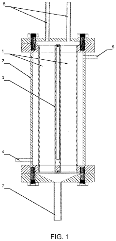
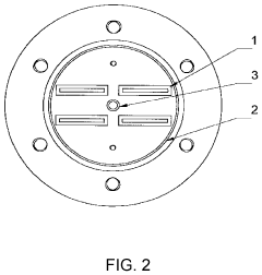
[0044]The structure of a compact reactor for the production of synthetic hydrocarbons in a Fischer-Tropsch process includes a housing containing four reaction channels filled with a cobalt catalyst containing 44.0 wt. % Co and 56.0 wt. % ZrO2; wherein the reaction channels has a thickness of 4 mm, a width-to-thickness ratio of 10, and a height-to-thickness ratio of 2000 and are placed in an outer housing sealed with two flange connections. The thickness of the wall of the reaction channel is 1.5 mm. The distance between the nearest reaction channels is 3 mm. The ratio of the total cross-sectional area of the channels to the cross-sectional area of the housing is 0.17. To obtain a uniform flow distribution of feedstock, the ratio of the number of channels to the number of synthesis gas injection nozzles is 2. A pressure controller is installed on an output nozzle. The outer surface of the channels with a catalyst has a roughness of 25 μm.

[0045]The cobalt catalyst consisting of 44.0 w...

example 2

[0052]The structure of a compact reactor for the production of synthetic hydrocarbons in a Fischer-Tropsch process includes a housing containing 50 reaction channels filled with a cobalt catalyst containing 46.0 wt. % Co, 13.5 wt. % ZrO2, and 40.5 wt. % SiO2; wherein the reaction channels has a thickness of 1 mm, a width-to-thickness ratio of 2, and a height-to-thickness ratio of 400 and are placed in an outer housing sealed with two flange connections. The thickness of the wall of the reaction channel is 1 mm. The distance between the nearest reaction channels is 1 mm. The ratio of the total cross-sectional area of the channels to the cross-sectional area of the housing is 0.89. To obtain a uniform flow distribution of feedstock, the ratio of the number of channels to the number of synthesis gas injection nozzles is 50. A pressure controller is installed on an output nozzle. The outer surface of the channels with a catalyst has a roughness of 11 μm.

[0053]The catalyst consisting of ...

example 3

[0060]The structure of a compact reactor for the production of synthetic hydrocarbons in a Fischer-Tropsch process includes a housing containing eight reaction channels filled with a cobalt catalyst containing 48.0 wt. % Co, 2.0 wt. % Re, and 50.0 wt. % ZrO2; wherein the reaction channels has a thickness of 5 mm, a width-to-thickness ratio of 100, and a height-to-thickness ratio of 1000 and are placed in an outer housing sealed with two flange connections. The thickness of the wall of said reaction channel is 3 mm. The distance between the nearest reaction channels is 5 mm. The ratio of the total cross-sectional area of the channels to the cross-sectional area of the housing is 0.38. To obtain a uniform flow distribution of feedstock, the ratio of the number of channels to the number of synthesis gas injection nozzles is 1. A pressure controller is installed on an output nozzle. The outer surface of the channels with a catalyst has a roughness of 1.6 μm.

[0061]The cobalt catalyst con...


PUM

PropertyMeasurementUnit
Temperatureaaaaaaaaaa
Timeaaaaaaaaaa
Pressureaaaaaaaaaa

Abstract

The invention relates to Fischer-Tropsch synthesis in a compact version. A compact reactor comprises a housing, rectangular reaction channels inside the housing, which are filled with a cobalt catalyst, synthesis gas injection nozzles in the number determined by the ratio of the number of channels to the number of synthesis gas injection nozzles, an input and output nozzle for heat transfer medium on which a pressure controller installed, and an assembly for withdrawing synthetic hydrocarbons. The cobalt catalyst is activated by passing hydrogen through it. Synthetic hydrocarbons are produced by passing synthesis gas through the reaction channels filled with the activated cobalt catalyst. The space velocity of synthesis gas is increased every 300-500 h, followed by returning to the initial process conditions. This provides a high-molecular-weight hydrocarbon output per unit mass of the reactor.

Description

TECHNICAL FIELD[0001]The invention relates to the field of oil, gas and coal chemistry and concerns Fischer-Tropsch synthesis, in particular, a reactor for producing synthetic hydrocarbons by a Fischer-Tropsch process and a method for conducting a Fischer-Tropsch synthesis reaction in a compact version.BACKGROUND[0002]Many companies are working on the implementation of compact mobile technologies for processing natural gas into synthetic hydrocarbons. The main advantage of such technologies is their possibility of use in small and distant hydrocarbon fields. In particular, they are focused on processing associated petroleum gas (APG), a significant part of which is burned off at fields. The Fischer-Tropsch synthesis technology in a compact version will improve the utilization of APG and natural gas in small and distant fields, thus increasing the profitability of their development.[0003]Compact reactor dimensions are driven by the need for transportation of Fischer-Tropsch synthesis...

Claims


Application Information

Patent Timeline
IPC IPC(8): B01J19/24C07C1/04B01J8/06
CPCC07C1/041C07C1/042B01J2208/00902B01J2208/06B01J2208/00539B01J19/249C10G2/00B01J2208/00557C10G2/30C10G2/32C10G2/34C10G2/332B01J8/06B01J8/001B01J8/065B01J8/067B01J21/066B01J21/12B01J23/75B01J23/8913B01J37/18B01J2208/0007B01J2208/00212B01J2208/00734B01J2219/1923B01J2523/00B01J19/2445B01J38/10C10G2/341C01B2203/062
Inventor MIKHAJLOV, MIKHAIL NIKOLAEVICHGRIGOR'EV, DMITRIJ ALEKSANDROVICHPROTASOV, OLEG NIKOLAEVICHMAMONOV, NIKOLAJ ALEKSANDROVICHBESSUDNOV, ALEKSEJ EDUARDOVICHSTUPAKOV, PAVEL MIKHAJLOVICHSANDIN, ALEKSANDR VASIL'EVICH
Owner ROSNEFT OIL CO ROSNEFT