
Thermal conductive member and heat dissipation structure including the same

Active Publication Date: 2020-01-30
DENKA CO LTD
View PDF4 Cites 1 Cited by
  • Summary
  • Abstract
  • Description
  • Claims
  • Application Information

AI Technical Summary

Benefits of technology

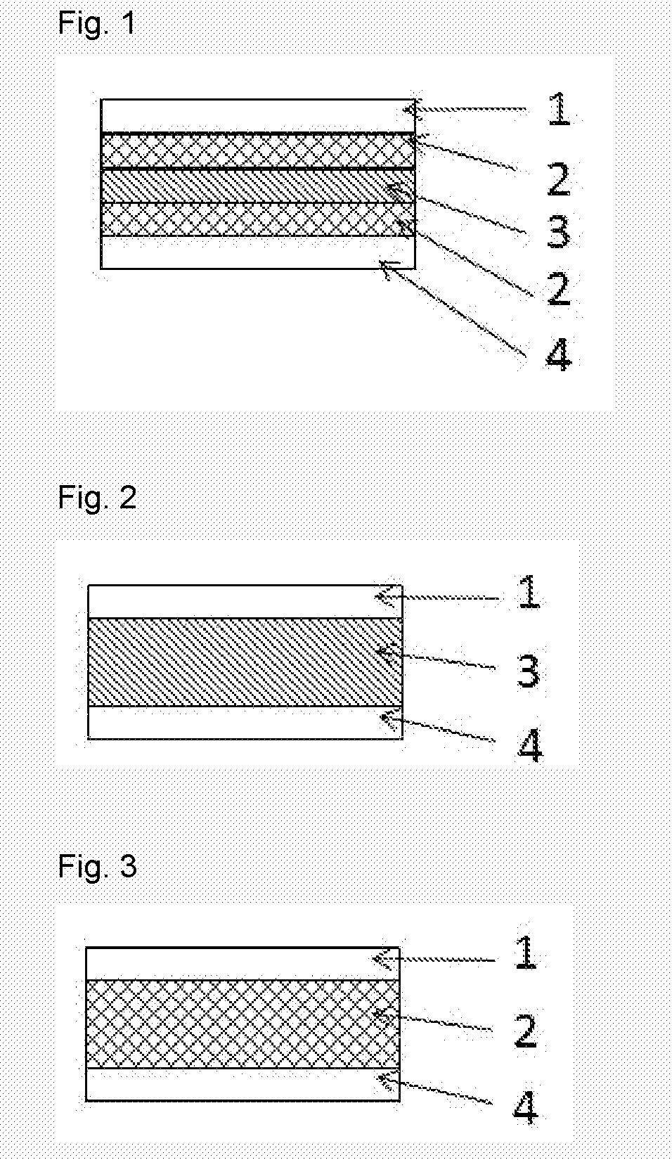
The present invention is able to provide a thermal conductive member that has better heat dissipation and smaller differences in thermal conductivity compared to previous methods. This is achieved by using two layers of insulating material, one layer made of a resin with small anisotropy in thermal conductivity and another layer made of a resin with larger anisotropy in thermal conductivity and higher thermal conductivity. This setup results in a more efficient transfer of heat.

Problems solved by technology

Accordingly, when the in-plane direction (a-axis direction) of the boron nitride particles is perpendicular to the thickness direction of the thermal interface material, for example, during manufacturing the thermal interface materials, the higher thermal conductivity of the in-plane direction (a-axis direction) of the boron nitride particles could not be sufficiently effective.
However, the conventional method of Patent Document 1 cannot reduce the anisotropy of the thermal conductivity, because the flake-shape boron nitride particles are oriented in one direction.
The conventional thermal conductive member used in the electronic components and having larger anisotropy have been facing the difficulty in achieving further minimization of the electronic devices, because the cooling unit and the heat transport unit cannot be disposed freely.
Although such method improves the anisotropy of the thermal conductivity, the IOP of the boron nitride particles decreases and the thermal conductivity in the in-plane direction (a-axis direction) of 400 W / (m·K) is not utilized efficiently, resulting in insufficient improvement of the thermal conductivity.

Method used


Image

  • Thermal conductive member and heat dissipation structure including the same

Examples


example 1

[0060]17.50% by mass of amorphous boron nitride powder (“SP” manufactured by Denka Co., Ltd.), 7.5% by mass of hexagonal boron nitride powder (“MGP” manufactured by Denka Co., Ltd.), and 0.47% by mass of calcium carbonate (“PC-700” manufactured by Shiroishi Kogyo Co., Ltd.) were mixed with a Henschel mixer, and then 74.53% by mass of water was added and grounded in a ball mill for 5 hours to obtain a water slurry. Furthermore, 0.5% by mass of polyvinyl alcohol resin (“Gosenol” manufactured by Nippon Synthetic Chemical Co., Ltd.) was added with respect to the total mass of the obtained water slurry, and heat-stirred at 50° C. to be dissolved. After that, the spheroidizing treatment was performed by a spray dryer at 230° C. of a drying temperature. A rotary atomizer was used for the spray dryer as the spheroidizing device. The resulting treated product was filled in a boron nitride container and sintered at 2000° C. of atmospheric pressure and 5 L / min of a nitrogen flow rate in a batc...

example 2

[0069]In Example 2, the sintering temperature was set to 2100° C. for preparing the boron nitride sintered body in the production of the insulating material A, which is different from Example 1.

example 3

[0070]In Example 3, the sintering temperature was set to 1800° C. for preparing the boron nitride sintered body in the production of the insulating material A, which is different from Example 1.


PUM

PropertyMeasurementUnit
Percent by volumeaaaaaaaaaa
Fractionaaaaaaaaaa

Abstract

A thermal conductive member includes: first and second surface layers including an insulating material A, and an intermediate layer including an insulating material B. The insulating material A includes a first boron nitride sintered body having an orientation degree of hexagonal boron nitride primary particles of 0.6 to 1.4, and a first heat curable resin composition impregnating in the first boron nitride sintered body. The insulating material B includes a second boron nitride sintered body having an orientation degree of hexagonal boron nitride primary particles of 0.01 to 0.05, and a second heat curable resin composition impregnating in the second boron nitride sintered body.

Description

TECHNICAL FIELD[0001]The present invention provides a thermal conductive member having a small thermal conductivity anisotropy and higher reliability, and a heat dissipation structure including the same.BACKGROUND ART[0002]Heat-generating electronic components such as power devices, double-side heat dissipation transistors, thyristors, and CPUs are facing an important task of efficient heat dissipation during their use. Conventionally, some heat dissipation measures have been conducted: (1) improving thermal conductivity of an insulating layer in a printed-wiring board (or printed circuit board) onto which the heat-generating electronic components are to be mounted, and (2) attaching the heat-generating electronic components or the printed-wiring board having the heat-generating electronic components to a heatsink via thermal interface materials having electric insulation. A thermal conductive member obtained by curing silicone resin and epoxy resin added with ceramics powder is use...

Claims


Application Information

Patent Timeline
IPC IPC(8): C04B35/583C04B41/83H01L23/373H01L23/34
CPCC04B2111/00465H01L23/373C04B41/83H01L23/345C04B35/583C04B2235/386C08K3/38H01L23/42H01L23/3735H01L23/3731H01L23/3737B32B18/00C04B41/009C04B41/4884C04B2235/3208C04B2235/442C04B35/6263C04B35/62655C04B2235/528C04B2235/3895C04B2235/6586C04B2237/361C04B35/645C04B2237/588C04B41/4853H01L23/15B32B9/00C08L101/12H05K7/20
Inventor INOUE, SAORIYAMAGATA, TOSHITAKAMINAKATA, YOSHITAKAYOSHIMATSU, RYOKOGA, RYUJI
Owner DENKA CO LTD
Learn More