Plasma texturing and coating method for frictional and thermal management

a technology of thermal management and texturing, applied in the direction of coatings, mechanical equipment, machines/engines, etc., can solve the problems of slowing down the technology transfer process from research labs to industrial applications, high energy waste of internal combustion engines (ice) and other machines, and expensive or time-consuming above methods, etc., to achieve improved friction and wear, and increase surface hardness

Inactive Publication Date: 2020-03-05
ZHANG JINGZENG +2
View PDF0 Cites 1 Cited by
  • Summary
  • Abstract
  • Description
  • Claims
  • Application Information

AI Technical Summary

Benefits of technology

[0007]The invention hereby deals with a method of making crater-like texture and coating on a component surface. This invented method is related to electrolytic plasma discharging, wherein said surface is connected to a power supply and in contact with an aqueous electrolyte. During the plasma discharging, the outmost layer of the surface is locally melt due to high temperature of plasma sparks, generating craters due to the collapse-induced pressure of vapour bubbles of the electrolyte; the melt is then solidified to have nanocrystalline structures which leads to have an increased surface hardness. Alternatively, chemical elements or compounds in the aqueous solution can be absorbed and sintered to form a ceramic coating on the component surface. After the surface is polished, ground or honed, the surface can have a mirror-like finish. The surface would show the improved friction and wear and temperature swing property.

Problems solved by technology

Friction and heat loss causes massive energy waste of internal combustion engine (ICE) and other machines which have rotating or sliding moving parts.
However, the above methods are usually costly or time-consuming; the drawbacks slow down the technology transferring process from research labs to industrial applications.
However, the cathodic plasma electrolysis has not been proposed to amend surface texture for applications in frictional and thermal management.
However, the anodic plasma electrolysis has not been proposed to make ceramic coatings on cast iron and steel components for frictional and thermal management in automotive applications yet.
In fact, it is very difficult to use the plasma electrolytic oxidation method to deposit ceramic coatings on an actual component made of the ferrous alloys although it may be possible to do that for a small sample of cast iron or steel.
In said method, an electrolyte is sprayed onto local surface areas with a relatively small surface coverage size, which can avoid the need of a huge power supply for working on an actual component; otherwise, the plasma discharging can not be appropriately generated on the surface of a large component.
The high temperature of plasma and high pressure of vapour bubbles at the local arc discharging spots during the plasma activities cause micro-sized craters on the surface.

Method used


Image

  • Plasma texturing and coating method for frictional and thermal management
  • Plasma texturing and coating method for frictional and thermal management
  • Plasma texturing and coating method for frictional and thermal management

Examples


Embodiment Construction

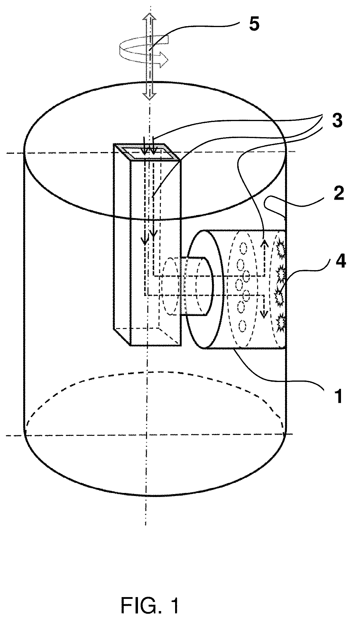
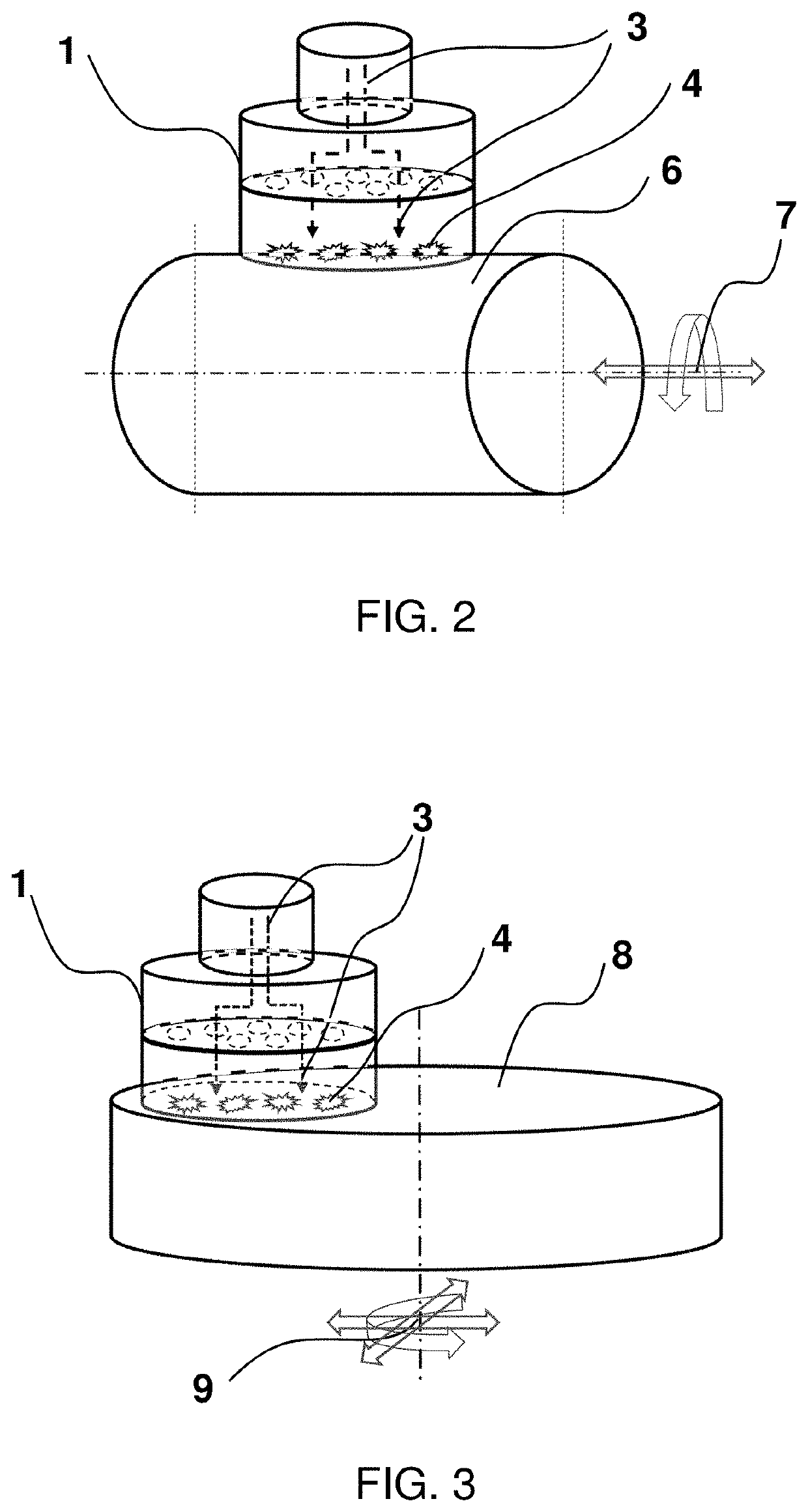
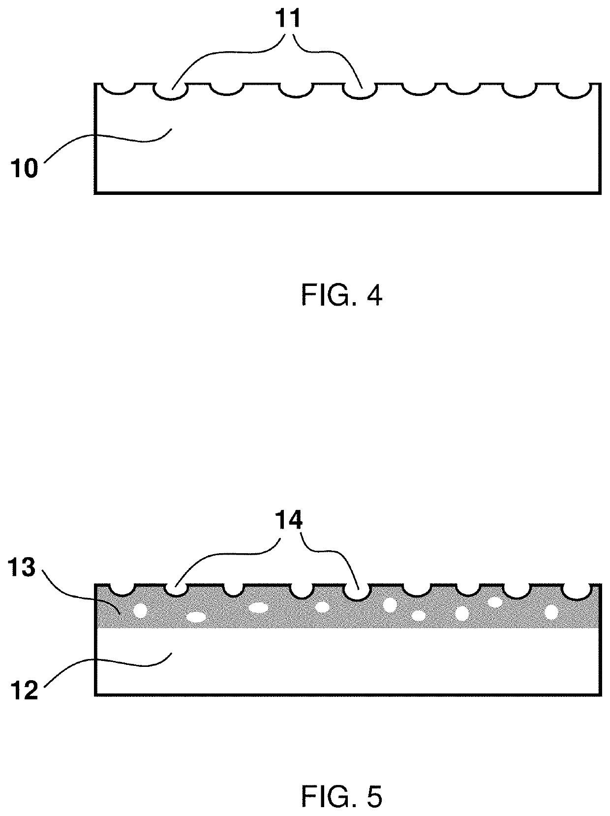
[0046]Referring to the schematic illustration in FIG. 1, a metallic spraying head 1 provides an inner surface 2 of a metallic component with an aqueous electrolyte 3; when a power supply applies electrical current and voltage between the spraying head 1 and the component 2, plasma discharges 4 are generated on the surface 2 of the component. The plasma discharges 4 are created by generating vapors and gases from the electrolyte on the surface 2 due to the heating from the applied electrical power energy initially and then breaking-down the vapors and gases under the applied voltage. Alternatively, the plasma discharges 4 can be created by absorbing at least one compound from the electrolyte to form a low electrical conductive layer on the surface 2 of the component first and then generating the electrical discharging due to the dielectric discharges of the layer under the applied voltage. The spraying head 1 can have motions 5 of rotations and moving up and down so that the entire i...


PUM

PropertyMeasurementUnit
current densityaaaaaaaaaa
thicknessaaaaaaaaaa
thermal conductivityaaaaaaaaaa

Abstract

This invention involves a method of making a crater-like texture or a ceramic coating on a surface by electrolytic plasma discharging which occurs in fashion of micro-sized arcs distributing on the surface. The high temperature of plasma and high pressure of vapour bubbles of an electrolyte at the local discharging spots during the plasma activities cause micro-sized craters on the surface. Alternatively, using another selected electrolyte, the surface can also form a ceramic coating with a crater-like texture as its top layer. The surface can be polished, ground or honed afterward, and the surface shows improvements in friction, wear resistance, and heat transfer behavior.

Description

TECHNICAL FIELD[0001]This invention involves a method of making a crater-like texture or coating on a component surface for performance improvement of friction and wear as well as thermal property and heat transfer behavior.BACKGROUND OF THE INVENTION[0002]Friction and heat loss causes massive energy waste of internal combustion engine (ICE) and other machines which have rotating or sliding moving parts. The coefficient of friction quite depends on surface texture, morphology and surface roughness of those parts. To reduce the friction, much research has been placed on alternation of surface texture using various CNC machining, EDM (electrical discharging machining) patterning, chemical etching, and laser patterning. The texture can be a grooved, cross-hatched, squared, rectangular, triangular, dotted or dimpled shape with different size, depth and areal density. However, the above methods are usually costly or time-consuming; the drawbacks slow down the technology transferring proc...

Claims


Application Information

Patent Timeline
Patent Type & Authority Applications(United States)
IPC IPC(8): C25D11/02F02F3/14F02F1/00F02F1/24F02F7/00
CPCF02F3/14C25D11/026F02F1/24F02F7/0087F02F1/004C25D11/26C25D11/04C25D11/34
Inventor ZHANG, JINGZENGNIE, YININGNIE, XUEYUAN
Owner ZHANG JINGZENG
Why Eureka
Try Eureka