Integrated chemical looping combustion system and method for power generation and carbon dioxide capture

a looping combustion and integrated technology, applied in the direction of fluidised bed combustion apparatus, machine/engine, combustion of combustible gas, etc., can solve the problems of increasing cosub>2 /sub>capture cost, yan's system does not include a gasification subsystem, and affecting the overall combustion efficiency

Active Publication Date: 2020-03-26
KING FAHD UNIVERSITY OF PETROLEUM AND MINERALS
View PDF8 Cites 4 Cited by
  • Summary
  • Abstract
  • Description
  • Claims
  • Application Information

AI Technical Summary

Benefits of technology

[0042]The HRSG subsystem may further comprise (d-ii) a second heat exchanger located downstream of, and fluidly connected to, the reducer and the first heat exchanger, wherein the second heat exchanger is configured to form steam at no higher temperature than the first heat exchanger by heating a water stream with the CO2/H2O stream.
[0043]The power generation subsystem may further comprise (c-iv) a second steam turbine located downstream of, and fluidly connected to, the second heat exchanger, wherein the second steam turbine operates at no higher pressure than the first steam turbine, and wherein the second steam turbine is configured to generate steam turbine shaft work with the steam.
[004

Problems solved by technology

These technologies can provide substantially pure CO2 separation from flue gases, though they are energy intensive, undermining the overall combustion efficiency and increase CO2 capture cost.
However, Yan's system does not include a gasification subsystem to form syngas or a gas splitter feeding gasified fuel directly to a combustor prior to any turbines, particularly without any intervening reactive or separative components.
However, Guillou's system lacks a power generation subsystem and is furthermore silent on a gas splitter in its system.
Guillou's does not disclose further processing its syngas—generated in a fluidized bed gasification reactor downstream of its oxidation-reduction loop.
In addition, Hoteit '546 is silent on gasification and fails to produce syngas, beyond trace byproducts, in its arrangement.
Second, power is generated by an advanced super critical steam cycle.
However, Kidambi's system does not include a power generation subsystem, i.e., for generating power, in its system.
However, Li's system, among other

Method used


Image

  • Integrated chemical looping combustion system and method for power generation and carbon dioxide capture
  • Integrated chemical looping combustion system and method for power generation and carbon dioxide capture
  • Integrated chemical looping combustion system and method for power generation and carbon dioxide capture

Examples


Embodiment Construction

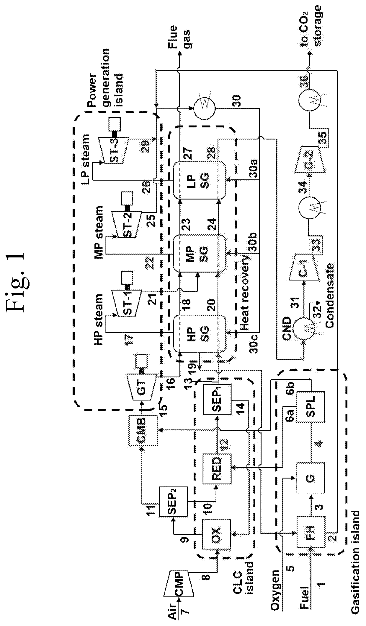
[0065]Aspects of the invention provide integrated systems, comprising a gasification subsystem, a chemical looping combustion (CLC) subsystem, a power generation subsystem, and a heat recovery-steam generation (HRSG) subsystem, and particularly comprising a gas splitter located downstream of, and fluidly connected to, a gasifier, which gas splitter is configured to split the syngas stream (primarily H2 and CO) from the gasifier into a first syngas substream and a second syngas substream, wherein one or both of these substreams are (directly) sent to separate stages in the CLC process. The first substream may be sent to a reducer / reduction reactor, while the second substream is fed directly to a combustor / combustion reactor, one or preferably both, prior to any turbines, particularly without any intervening reactive or separative components between the splitter and the reducer and / or combustor. The splitter may be configured to separate out particular components of the gasification ...


PUM


Abstract

A chemical looping combustion (CLC) based power generation, particularly using liquid fuel, ensures substantially complete fuel combustion and provides electrical efficiency without exposing metal oxide based oxygen carrier to high temperature redox process. An integrated fuel gasification (reforming)-CLC-followed by power generation model is provided involving (i) a gasification island, (ii) CLC island, (iii) heat recovery unit, and (iv) power generation system. To improve electrical efficiency, a fraction of the gasified fuel may be directly fed, or bypass the CLC, to a combustor upstream of one or more gas turbines. This splitting approach ensures higher temperature (efficiency) in the gas turbine inlet. The inert mass ratio, air flow rate to the oxidation reactor, and pressure of the system may be tailored to affect the performance of the integrated CLC system and process.

Description

STATEMENT OF ACKNOWLEDGEMENT[0001]The financial support provided by King Abdul Aziz City for Science and Technology (KACST) under KACST-TIC for CCS project no. 03 and the facilities and support provided by King Fand University of Petroleum and Minerals (KFUPM) is gratefully acknowledged.BACKGROUND OF THE INVENTIONField of the Invention[0002]This application relates to chemical looping combustion (CLC) based power generation, particularly sequestering CO2.Description of the Related Art[0003]The combustion of fossil fuel in power generation has been reported to contribute one third of the total worldwide CO2 emission, believed responsible for global warming. A number of CO2 sequestration technologies, both pre-combustion and post-combustion, are being developed under efforts to reduce CO2 emissions. These technologies can provide substantially pure CO2 separation from flue gases, though they are energy intensive, undermining the overall combustion efficiency and increase CO2 capture c...

Claims


Application Information

Patent Timeline
IPC IPC(8): F01K23/10F02C3/20F23C10/01F23C10/04F23C13/08F23C10/22F23R3/40C01B3/02C10J3/82C10J3/50
CPCF02C3/28C10J3/82F23R3/40F23C10/01C10J2300/1687F02C3/205F01K23/108C10J2300/1675F23C13/08C10J2300/1884C10J3/503F23C10/22C10J2300/1215F23C10/04C10J2300/1823C01B3/02F05D2220/722F02C6/18F01K23/106F01K23/18C10J2300/1653F23C2900/99008F23K2300/204F23C2900/99011Y02E20/14Y02E20/16Y02E20/18Y02E20/34Y02P20/129Y02P20/10C01B3/36C01B2203/84F02C7/224
Inventor HOSSAIN, MOHAMMED MOZAHARADNAN, MUFLIH ARISA
Owner KING FAHD UNIVERSITY OF PETROLEUM AND MINERALS
Why Eureka
Try Eureka