Electret Energy Storage System

a technology of energy storage and electrochemical components, applied in the direction of variable capacitors, capacitors, electrical equipment, etc., can solve the problems of imposing significant constraints, unable to solve the problem of significant constraints, and the configuration of the dielectric material supporting ion flows between the conductive battery plates is not conducive to storing significant amounts of energy, etc., to increase the operational life of the constant voltage source, increase the high energy density level, and extend the operational life

Active Publication Date: 2020-03-26
ROSENER KIRK W
View PDF0 Cites 2 Cited by
  • Summary
  • Abstract
  • Description
  • Claims
  • Application Information

AI Technical Summary

Benefits of technology

[0050]One object of the invention is incorporating the EESS with traditional batteries into an integrated energy delivery solution. Most traditional energy consuming loads require a source of constant voltage. Combining the EESS (a constant current source) in parallel with a constant voltage source provides a synergistic solution in supplying energy to loads that significantly extends the operational life of the constant voltage source. A synergistic contribution of this approach also increases high energy density levels from the combined devices as well as increasing the operational life of the constant voltage source.
[0051]An additional object of the EESS is the ability is to significantly reduce the traditional time frame for externally recharging batteries that have been integrated into an EESS based solution. Energy transfer rates are significantly faster when they occur between a charged EESS reservoir and a second depleted EESS reservoir integrated with a traditional battery. This alternative advantage provides significantly faster system level energy recharge rates over time as compared to the traditional battery only recharge rates over time into the conductive plates of batteries.
[0052]An additional advantage of an EESS integrated energy delivery solution is lower weight per unit area. This advantage provides significant reductions in the combined EESS / battery high energy density storage / delivery footprint solution. This approach also provides rapid boosts of power supporting demand loads requiring high levels of power density per unit of time. This occurs through integrated EESS / battery solutions providing higher levels of effective energy capacities compared to traditional battery-only solutions.
[0053]Key advantages of the EESS at the system level are grouped into five areas. The cumulative contribution of sub-elements results in each advantage providing an energy storage device lasting from weeks to months supplying high rates of energy retention at low leakage levels. In addition the advantages of the EESS reduces the energy storage / watt footprint by orders of magnitude compared to traditional standalone battery and super capacitor energy storage technologies having equivalent energy storage capacities per unit area.
[0054]The unique characteristic of each of the following four advantages provides a synergistic contribution that is greater than the sum of the contributions from each key area as they are combined within the EESS architecture. An integrated EESS apparatus overcomes limitations of storing energy on conductive plates by taking advantage of storing energy within the electric fields residing within the electret storage areas by incorporating:
[0055]Key Advantage 1 maximizes the high energy density storage capacity per unit area in each electret energy storage reservoir cell by capturing and retaining electric field energy provided from high energy bremsstrahlung photons as move through each cell. These photons distribute energy within previously established high capacity electric field density capabilities residing within the dielectric material of each asymmetric energy storage cell.

Problems solved by technology

Furthermore no solutions have been found in the art where the levels of energy storage density per unit area, combined with extended energy storage times described in this specification have been achieved.
This methodology imposes significant constraints on the chemical makeup of the dielectric selected limiting the amount of energy that can be stored within the electric charge density field of the dielectric materials used in these devices.
The physics of the configuration of the dielectric material supporting ion flows between the conductive battery plates is not conducive to storing significant amounts of energy within electric charge density fields residing within the dielectric material of the battery itself.
Although the stored energy density of a typical chemical battery is quite high when compared to that of a typical capacitor, the voltage levels of each battery cell of a battery are limited to the single digit voltage range.
The functional lifetime of a traditional battery cell is limited due to irreversible chemical side reactions at the electrodes.
However, since these type of electrolytes are flammable there is an upper energy storage safety limit that cannot be passed on these types of batteries due to the increased risks of the battery catching on fire.
This limitation is not imposed on traditional electret manufacturing solutions due to these types of flammable electrolytes not possessing desired dielectric material characteristics in forming electrets.
Thus most capacitor and super capacitor cell designs are not able to take advantage of increasing the voltage levels to be stored within increasing thicknesses of the conductive capacitor plates due to the loss of desired capacitance values and low voltage level constraints.
The inherent capability of dielectrics used within capacitors to prevent electric breakdowns occurring between the plates of a capacitor are very inefficient with respect to storing energy within the electric charge density field of the capacitor dielectric.
In addition incorporation of higher voltage levels to take advantage of voltage squared capabilities to increase energy densities per unit area that can be achieved within electret dielectric formulations is not pursued due to traditional voltage breakdown design constraints.
Traditional capacitor and ultra-capacitors experience high levels of current leakage at high voltages due to the constraints imposed by the types of materials used in separating the plates of a capacitor.
From a power transfer perspective, capacitors and supercapacitors are limited due to high levels of Equivalent Series Resistance (ESR) imposed by traditional capacitor dielectric materials and their reliance on storing and extracting conductive energy on the conductive plates of the capacitor.
This unique capability of the EESS methodology focuses on increasing energy storage densities by the square of the voltage as reflected by Plank's equation (energy stored=CV2), rather being limited to primarily using methods to increase the capacitance within traditional electrical energy storage devices.
The energy density per unit area electret storage capacity established as described in the Berggren process is severely limited by the significantly lower voltage rise times and energy levels of the alpha particles used in his experiments.

Method used


Image

  • Electret Energy Storage System
  • Electret Energy Storage System
  • Electret Energy Storage System

Examples


Embodiment Construction

—FIG. 1 THROUGH FIG. 10—PREFERRED EMBODIMENT

[0095]The preferred embodiment of the EESS invention performs as an energy storage device ranging from kilowatts to megawatts at increased energy densities per unit area. The EESS energy storage density per unit area footprint is significantly less than traditional energy storage technologies that have previously been reported within the energy storage art. Expected energy retention times range from days to months at low levels of energy leakage.

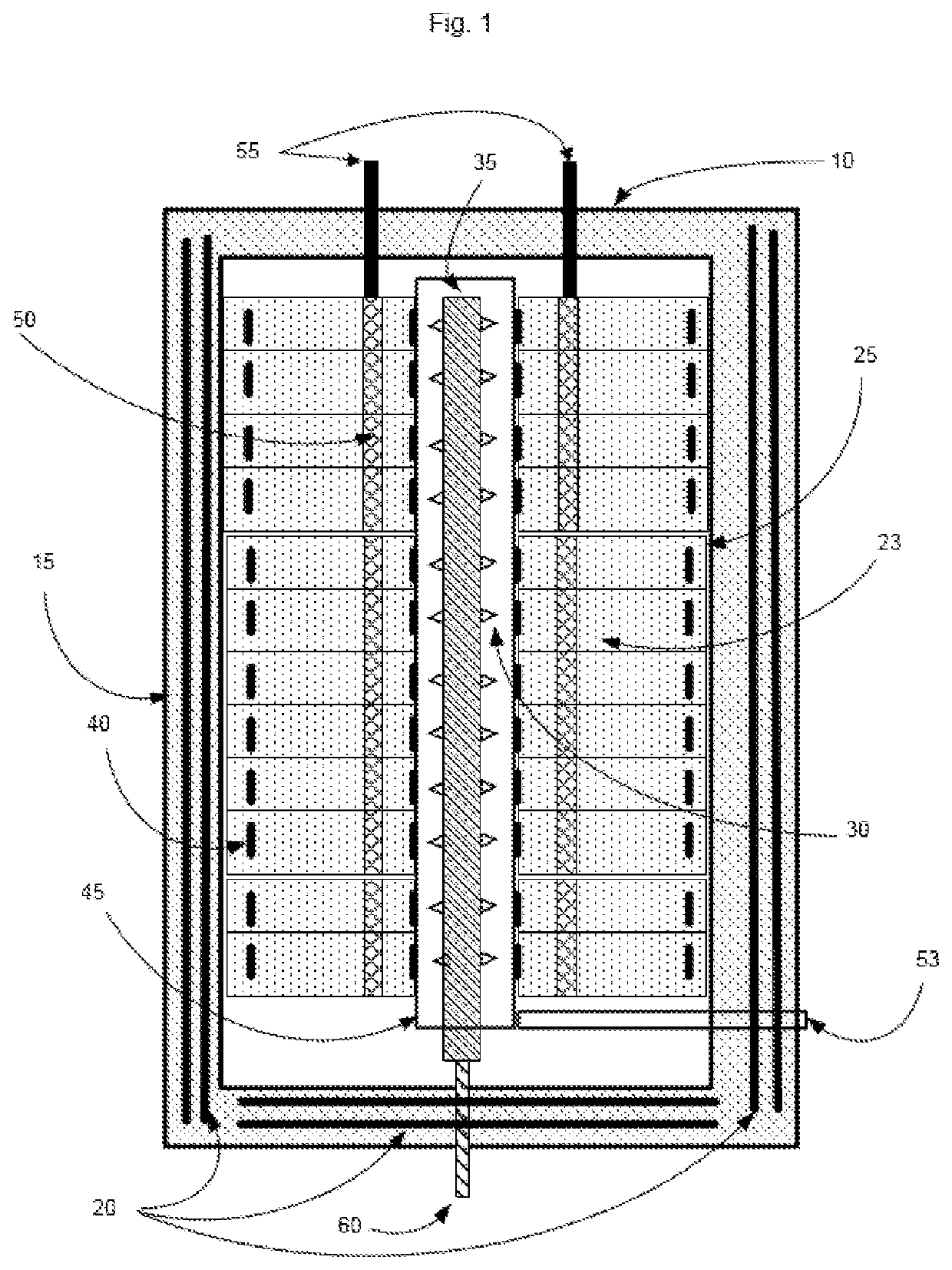
[0096]The energy storage reservoir (10) depicted in FIG. 1 completely encases all electret energy storage reservoir cells (23) that are encapsulated by the EESS paramagnetic material (15). During the charging period of each electret energy storage reservoir cell (23), a vacuum is maintained with the bremsstrahlung charge tube (45). The charge point cells (30), attached to the charge tube (35) fire energetic charged particles into the bremsstrahlung charge tube (45) connected to the front end of eac...


PUM


Abstract

The Electret Energy Storage System (EESS) achieves an advancement in the energy storage field due to high energy/power level densities integrated into a long term energy storage solution. Combining the high density energy storage solution of the EESS with traditional battery storage technologies reduces the overall energy storage three dimensional footprint when compared to battery only footprints. This combined EESS/battery long term energy storage provides a solution in providing energy from renewable energy systems when the presence of the wind or sun are not available when compared to traditional battery only storage solutions.

Description

BACKGROUND OF THE INVENTIONField of Invention[0001]The Electret Energy Storage System (EESS) achieves a significant advancement in the energy storage field due to high energy / power level densities integrated into a novel long term energy storage solution. Combining the high voltage solution of the EESS with traditional battery storage technologies significantly increases energy densities per unit area, thereby reducing the overall energy storage footprint. This combined EESS / battery long term energy storage provides a cost effective solution in providing energy from renewable energy systems when the presence of the wind or sun are not available when compared to traditional battery only storage solutions.[0002]Components of the EESS storage approach provide a novel integration of key principles surrounding the capture and storage of extremely high voltage energies. Penetration of dipole oriented electrets, including high dielectric plastics, waxes, or crystals, by energetic bremsstra...

Claims


Application Information

Patent Timeline
Patent Type & Authority Applications(United States)
IPC IPC(8): H01G7/02H01G11/30H01G11/26
CPCH01G7/02H01G11/30H01G11/26H01G7/023
Inventor ROSENER, KIRK W.
Owner ROSENER KIRK W
Why Eureka
Try Eureka