Logic drive based on multichip package using interconnection bridge

a logic drive and multi-chip technology, applied in the direction of logic circuits, logic circuit details, logiconductors/solid-state devices, etc., to achieve the effect of facilitating and reducing the cost of innovation

Active Publication Date: 2020-04-09
ICOMETRUE CO LTD
View PDF0 Cites 20 Cited by
  • Summary
  • Abstract
  • Description
  • Claims
  • Application Information

AI Technical Summary

Benefits of technology

[0005]Another aspect of the disclosure provides a method to reduce Non-Recurring Engineering (NRE) expenses for implementing an innovation and / or an application in semiconductor IC chips by using the standardized commodity logic drive comprising a plurality of standardized commodity FPGA IC chips. A person, user, or developer with an innovation and / or an application concept or idea needs to purchase the standardized commodity logic drive and develops or writes software codes or programs to load into the standardized commodity logic drive to implement his / her innovation and / or application concept or idea; wherein said innovation and / or application (maybe abbreviated as innovation) comprises (i) innovative algorithms and / or architectures of computing, processing, learning and / or inferencing, and / or (ii) innovative and / or specific applications. Compared to the implementation by developing a logic ASIC or COT IC chip, the NRE cost may be reduced by a factor of equal to or larger than 2, 5, 10, 30, 50 or 100 using the disclosed standardized commodity logic drive. For advanced semiconductor technology nodes or generations (for example more advanced than or below 20 nm or 10 nm), the NRE cost for designing an ASIC or COT chip increases greatly, more than US $10M or even exceeding US $20M, US $50M, US $100M, orUS $200M, as seen in FIG. 32. The cost of a photo mask set for an ASIC or COT chip at the 16 nm technology node or generation may be over US $5M, US $10M, or US $20M. Implementing the same or similar innovation and / or application using the logic drive may reduce the NRE cost down to smaller than US $10M or even less than US $5M, US $3M, US $2M or US $1M. The aspect of the disclosure inspires the innovation and lowers the barrier for implementing the innovation in IC chips designed and fabricated using an advanced IC technology node or generation, for example, a technology node or generation more advanced than or below 20 nm or 10 nm.
[0008]Another aspect of the disclosure provides a logic drive with high programmability and high efficiency using a multi-chip package comprising a plurality of FPGA IC chip, CPU chip, GPU chip, TPU chip and ASIC chip. The programmability of semiconductor IC chips decreases, in order, from FPGA IC chip, CPU chip, GPU chip, TPU chip to ASIC chip, while the efficiency of semiconductor IC chips increases, in order, from FPGA IC chip, CPU chip, GPU chip, TPU chip to ASIC chip, as illustrated in FIG. 31. The disclosed logic drive provides FPGA IC chips to improve the programmability of high efficient semiconductor IC chips, such as ASIC chip, TPU chip, GPU chip and CPU chip.
[0015]Another aspect of the disclosure provides the standard commodity logic drive in a multi-chip package comprising a plurality of standard commodity FPGA IC chips and one or a plurality of non-volatile memory IC chips, for use in different applications requiring logic, computing and / or processing functions by field programming, wherein the plurality of standard commodity FPGA IC chips, each is in a bare-die format or in a single-chip or multi-chip package. Each of the plurality of standard commodity FPGA IC chips may have standard common features or specifications: (1) logic blocks including (i) system gates with the count greater than or equal to 2M, 10M, 20M, 50M or 100M, (ii) logic cells or elements with the count greater than or equal to 64K, 128K, 512K, 1M, 4M or 8M, (iii) hard macros, for example DSP slices, microcontroller macros, multiplexer macros, fixed-wired adders, and / or fixed-wired multipliers and / or (iv) blocks of memory with the bit count equal to or greater than 1M, 10M, 50M, 100M, 200M or 500M bits; (2) the number of inputs to each of the logic blocks or operators: the number of inputs to each of the logic block or operator may be greater or equal to 4, 8, 16, 32, 64, 128, or 256; (3) the power supply voltage: the voltage may be between 0.1V and 2.5V, 0.1V and 2V, 0.1V and 1.5V, or 0.1V and 1V; (4) the I / O pads, in terms of layout, location, number and function. Since the FPGA chips are standard commodity IC chips, the number of FPGA chip designs or products is reduced to a small number, therefore, the expensive photo masks or mask sets for fabricating the FPGA chips using advanced semiconductor nodes or generations are reduced to a few mask sets. For example, reduced down to between 3 and 20 mask sets, 3 and 10 mask sets, or 3 and 5 mask sets for a specific technology node or generation. The NRE and production expenses are therefore greatly reduced. With the few designs and products, the manufacturing processes may be tuned or optimized for the few chip designs or products, and resulting in very high manufacturing chip yields. This is similar to the current advanced standard commodity DRAM or NAND flash memory design and production. Furthermore, the chip inventory management becomes easy, efficient and effective; therefore, resulting in a shorter FPGA chip delivery time and becoming very cost-effective.
[0018]Another aspect of the disclosure provides the standard commodity logic drive in a multi-chip package comprising a plurality of standard commodity FPGA IC chips and one or a plurality of non-volatile memory IC chips, for use in different algorithms, architectures and / or applications requiring logic, computing and / or processing functions by field programming, wherein the plurality of standard commodity FPGA IC chips, each is in a bare-die format or in a single-chip or multi-chip package format. The standard commodity logic drive may have standard common features, counts or specifications: (1) logic blocks including (i) system gates with the count greater than or equal to 8M, 40M, 80M, 200M or 400M, (ii) logic cells or elements with the count greater than or equal to 256K, 512K, 2M, 4M, 16M or 32M, (iii) hard macros, for example DSP slices, microcontroller macros, multiplexer macros, fixed-wired adders, and / or fixed-wired multipliers and / or (iv) blocks of memory with the bit count equal to or greater than 4M, 40M, 200M, 400M, 800M or 2 G bits; (2) the power supply voltage: the voltage may be between 0.1V and 12V, 0.1V and 7V, 0.1V and 3V, 0.1V and 2V, 0.1V and 1.5V, or 0.1V and 1V; (3) the I / O pads in the multi-chip package of the standard commodity logic drive, in terms of layout, location, number and function; wherein the logic drive may comprise the I / O pads, metal pillars or bumps connecting or coupling to one or a plurality of (2, 3, 4, or more than 4) Universal Serial Bus (USB) ports, one or a plurality of IEEE 1394 ports, one or a plurality of Ethernet ports, one or a plurality of audio ports or serial ports, for example, RS-232 or COM (communication) ports, wireless transceiver I / Os, and / or Bluetooth transceiver I / Os, and etc. The logic drive may also comprise the I / O pads, metal pillars or bumps connecting or coupling to Serial Advanced Technology Attachment (SATA) ports, or Peripheral Components Interconnect express (PCIe) ports for communicating, connecting or coupling with the memory device or drive. Since the logic drives are standard commodity products, the product inventory management becomes easy, efficient and effective, therefore resulting in a shorter logic drive delivery time and becoming cost-effective.

Problems solved by technology

However, when IC technology nodes migrate to a technology node more advanced than 20 nm, and for example to the technology nodes of 16 nm, 10 nm, 7 nm, 5 nm or 3 nm, only a few giant system or IC design companies, not the public innovators, can afford to use the semiconductor IC manufacturing foundry fab.

Method used


Image

  • Logic drive based on multichip package using interconnection bridge
  • Logic drive based on multichip package using interconnection bridge
  • Logic drive based on multichip package using interconnection bridge

Examples


Embodiment Construction

[0101]Illustrative embodiments are now described. Other embodiments may be used in addition or instead. Details that may be apparent or unnecessary may be omitted to save space or for a more effective presentation. Conversely, some embodiments may be practiced without all of the details that are disclosed.

[0102]Specification for Static Random-Access Memory (SRAM) Cells

[0103](1) First Type of Volatile Storage Unit

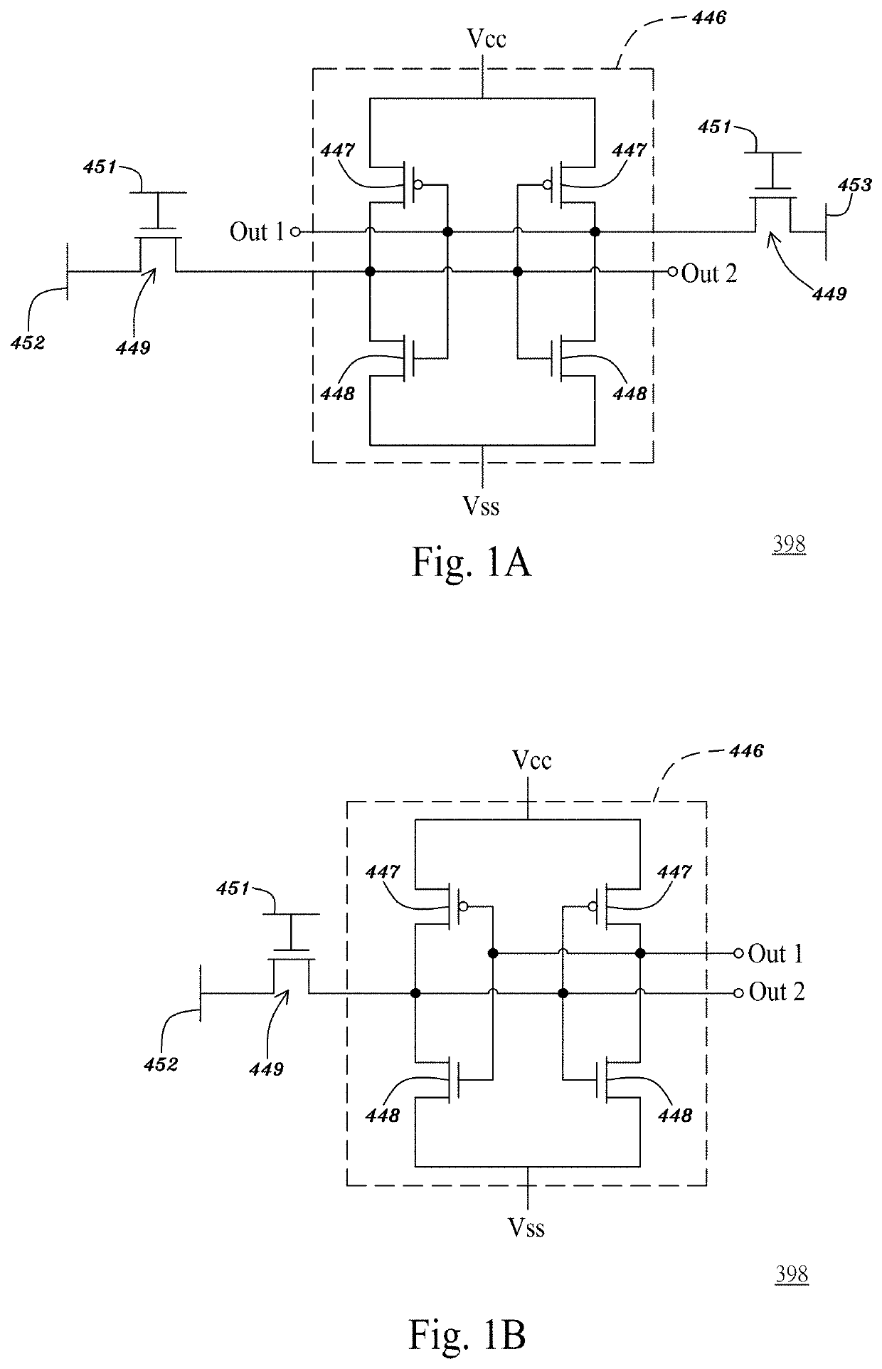
[0104]FIG. 1A is a circuit diagram illustrating a first type of volatile storage unit in accordance with an embodiment of the present application. Referring to FIG. 1A, a first type of volatile storage unit 398 may have a memory unit 446, i.e., static random-access memory (SRAM) cell, composed of 4 data-latch transistors 447 and 448, that is, two pairs of a P-type MOS transistor 447 and N-type MOS transistor 448 both having respective drain terminals coupled to each other, respective gate terminals coupled to each other and respective source terminals coupled to the voltage ...


PUM


Abstract

A multi-chip package comprising: an interconnection substrate comprising an interconnection bridge embedded in the interconnection substrate, and an interconnection scheme comprising a first interconnection metal layer, a second interconnection metal layer over the first interconnection layer and the interconnection bridge, and a polymer layer between the first and second interconnection metal layers, wherein the interconnection bridge is embedded in the interconnection scheme and has sidewalls surrounded by the polymer layer; a semiconductor IC chip over the interconnection substrate and across over an edge of the interconnection bridge; a memory chip over the interconnection substrate and across over an edge of the interconnection bridge, wherein the interconnection bridge comprises a plurality of metal interconnects configured for a data bus coupling the semiconductor IC chip to the memory chip, wherein a bitwidth of the data bus between the semiconductor IC chip and the memory chip is greater than or equal to 512.

Description

PRIORITY CLAIM[0001]This application claims priority benefits from U.S. provisional application No. 62 / 741,513, filed on Oct. 4, 2018 and entitled “LOGIC DRIVE BASED ON STANDARDIZED COMMODITY PROGRAMMABLE LOGIC SEMICONDUCTOR IC CHIPS”. The present application incorporates the foregoing disclosures herein by reference.BACKGROUND OF THE DISCLOSUREField of the Disclosure[0002]The present invention relates to a logic package, logic package drive, logic device, logic module, logic drive, logic disk, logic disk drive, logic solid-state disk, logic solid-state drive, Field Programmable Gate Array (FPGA) logic disk, FPGA logic drive, or programmable logic drive (to be abbreviated as “logic drive” below, that is when “logic drive” is mentioned below, it means and reads as “logic package, logic package drive, logic device, logic module, logic drive, logic disk, logic disk drive, logic solid-state disk, logic solid-state drive, FPGA logic disk, FPGA logic drive, or programmable logic drive”) c...

Claims


Application Information

Patent Timeline
Patent Type & Authority Applications(United States)
IPC IPC(8): H01L23/522H03K19/177H01L23/00H01L23/532
CPCH01L23/53238H01L23/5226H03K19/17708H01L24/09H01L23/5221H03K19/17728H03K19/17744H03K19/1776H01L24/17H01L2924/15192H01L2224/0401H01L2224/0603H01L2224/1703H01L2924/15311H01L2224/17181H01L2224/16227H01L2224/16145H01L2924/1533H01L2924/18161H01L2224/0557H01L2224/06181H01L2224/32145H01L2224/32225H01L2224/73204H01L2225/1041H01L2225/1058H01L2225/1023H01L2224/92125H01L2224/81204H01L2224/1403H01L2224/13147H01L2224/131H01L24/81H01L2224/97H01L2224/13082H01L2224/81447H01L24/05H01L24/06H01L24/13H01L24/14H01L24/16H01L24/32H01L24/92H01L25/0655H01L25/105H01L23/5383H01L23/5389H01L23/49816H01L23/5385H01L2924/00014H01L2924/014H01L2224/83H01L2224/81H01L2924/00H01L2224/16225H01L24/19H01L24/20H01L24/97H01L23/5386H01L25/0652H01L25/0657
Inventor LIN, MOU-SHIUNGLEE, JIN-YUAN
Owner ICOMETRUE CO LTD
Why Eureka
Try Eureka