
High Resolution Multiplexing System

a multiplexing system and high-resolution technology, applied in the field of high-resolution multiplexing system, can solve the problems of jitter, loss, and introduction of errors, and achieve the effect of reducing the error caused by jitter, and reducing the effect of gain and offset errors

Active Publication Date: 2020-05-14
11093568 CANADA LTD
View PDF0 Cites 4 Cited by
  • Summary
  • Abstract
  • Description
  • Claims
  • Application Information

AI Technical Summary

Benefits of technology

The patent describes a device that splits and conditions a signal, allowing for more efficient processing and improved signal-to-noise ratios. The device has multiple integration periods, which allows for the accumulation of signals over time and reduces errors caused by timing jitter. The device also reduces uncorrelated noise and errors caused by offset and gain errors in the analog-to-digital conversion process. Overall, the device provides improved performance and reliability for signal conditioning and processing.

Problems solved by technology

Generally, the precision of an ADC declines as the sampling rate increases and hence the precision of the particle flux measurement also declines.
An error is introduced because there is jitter in the timing signals.
Further errors are introduced variability between interleaved ADC's in a stack, specifically, there are offset and gain error.

Method used


Image

  • High Resolution Multiplexing System
  • High Resolution Multiplexing System
  • High Resolution Multiplexing System

Examples


Embodiment Construction

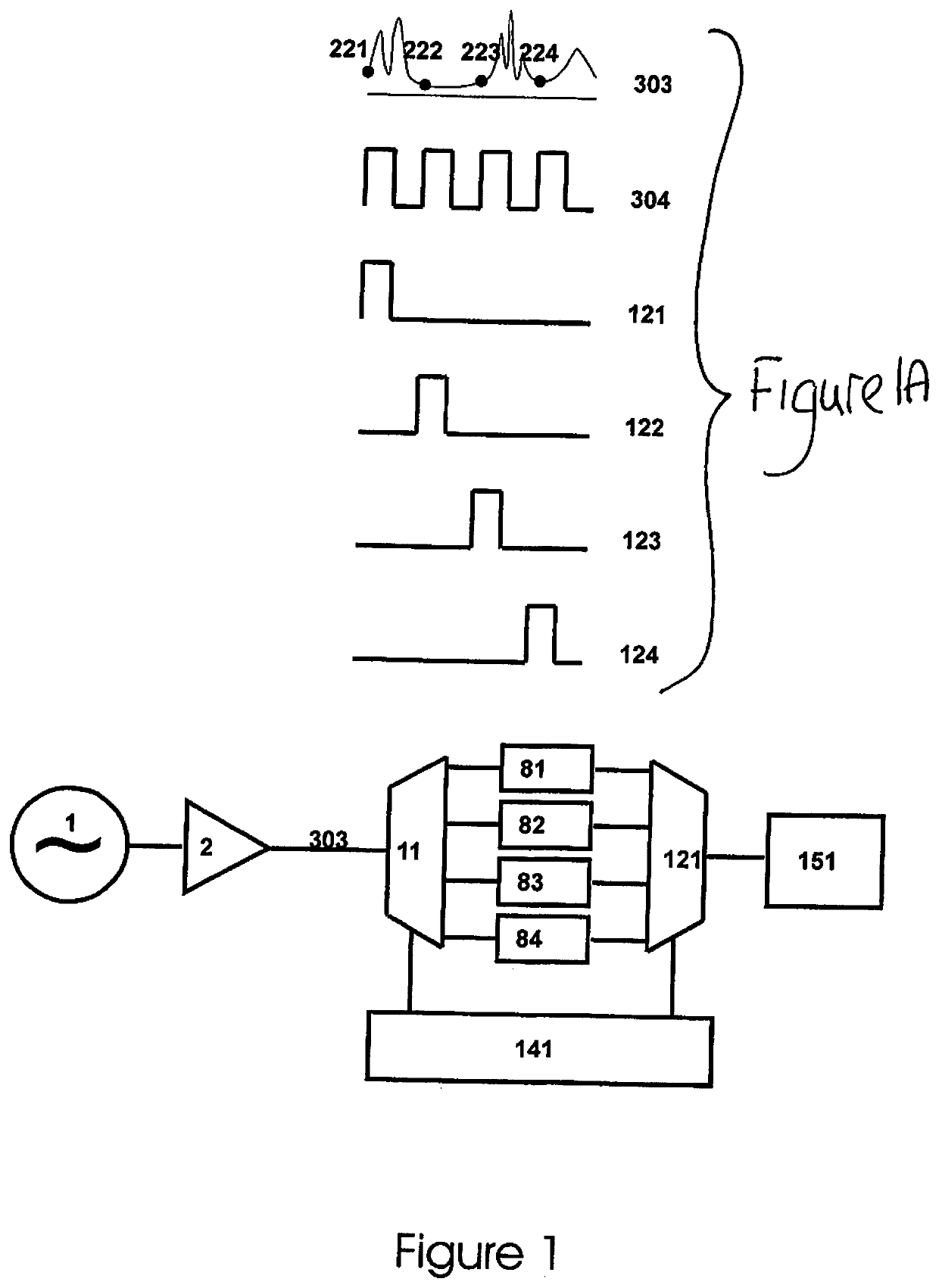
[0106]FIG. 1 shows a schematic view of a high speed analog to digital conversion system according to prior art. Analog input 1 is amplified 2 and the resulting analog signal 303 is transmitted to switch 11 connected to timing control 141. Each clock cycle at frequency f, timing control 141 increments the address of the ADC in stack to connect with the analog cycle and resets to the first address after the last address is connected. In the example shown, the ADC's in the stack are connected in the repeating sequence 81, 82, 83, 84. The clock input is indicated as 304 and the waveforms for ADC's 81, 82, 83, and 84 are indicated as 121, 122, 123 and 124, respectively. The value of the input signal 303 is captured on the rising edge of the timing pulse for each ADC. That is ADC's 81, 82, 83 and 84 read the signal at the indicated instants 221, 221, 223, and 224, respectively. Each ADC in the stack outputs a digital result at frequency f / N (f / 4 in the example shown) to interleaver 121, w...


PUM

PropertyMeasurementUnit
lengthaaaaaaaaaa
timeaaaaaaaaaa
photon flux amplitudeaaaaaaaaaa

Abstract

A method is provided for measuring time varying particle fluxes with improved temporal resolution and signal to noise ratio. The particles can be photons, neutrons, electrons or electrically charged particles. The method includes a set of electronic and / or optical components and a set of algorithms that implement N-fold temporal multiplexing of the input flux. The system can be used to measure other types of flux by using a transducer to convert the flux into a compatible form. The system can include a transducer such as a scintillator that operates to convert particle flux incident into a photon flux proportional to the amplitude of particle flux. The invention can be used with multiplexing methods known to those skilled in the art, for example Hadamard and Fourier methods.

Description

[0001]The invention pertains to a method and device for measuring time varying particle fluxes with improved temporal resolution and improved signal to noise ratio. The particles can be photons, neutrons, electrons and electrically charged particles.BACKGROUND OF THE INVENTION[0002]The amplitude of particle fluxes is conventionally measured by collecting the particle flux, directing the particle flux onto a transducer that produces an electrical signal (voltage or current) with amplitude proportional to the particle flux, conditioning the electric signal, and comparing the electric signal with a set of standard electric signals to assign a numeric value to the particle flux amplitude. The last step is conventionally done with analog to digital converters (ADC).[0003]Analog to digital converters act as an interface between analog electric signals and a digital computation device for applications that range from instrumentation, to radar to communications. Two main criteria are used t...

Claims


Application Information

Patent Timeline
Patent Type & Authority Applications(United States)
IPC IPC(8): G01N21/552G01J3/02G01N21/65
CPCG01N21/552G01N2021/3595G01J3/021G01J3/0294G01J3/0237G01N21/65G01J2001/442G01J1/44H03M1/145H03M1/121
Inventor PRYSTUPA, DAVID ALLANPACAK, JOHN STEPHENNELL, PETER CONDIE
Owner 11093568 CANADA LTD
Learn More