Laser driver

a laser driver and laser technology, applied in the field of laser driver, can solve the problems of waste of useful light by projectors or methods of operating these, and achieve the effects of reducing the number of different drive currents, and facilitating compensation for non-linear effects

Active Publication Date: 2020-07-09
BARCO NV
View PDF0 Cites 3 Cited by
  • Summary
  • Abstract
  • Description
  • Claims
  • Application Information

AI Technical Summary

Benefits of technology

[0016]characterized in that the first and second drive currents are calibrated so as to provide the pre-defined chromaticity of the combined beam over at least the first range of drive current values of the first and second laser driver. The removal of non-linear performance allows use of the projector into non-linear regions of the wavelength conversion element, without resulting in major shifts in the projector's whitepoint.
[0017]Reference to a laser also refers to a bank of lasers all producing laser light of a similar or same wavelength. Laser refers to laser diode but the invention is not limited thereto and can be used with other light sources such as solid-state light sources, such as light emitting diode, but also OLED. More generally, any type of light source suitable to excite a wavelength conversion element or a phosphor can be used for the present invention, as the present invention solves the problem of providing a constant chromaticity over a non-linear range of the wavelength conversion element. The intensity of the light in the first waveband can further also be controlled by the second drive current applied to the second laser driver. The intensity of the converted light beam can also further be controlled by the first drive current applied to the first laser driver. By using different laser drivers for different lasers or bank of lasers allows more accurate correction.
[0018]The plurality of first lasers emitting light in the first waveband can be in a laser bank, wherein each laser bank is controlled by a drive current applied to a laser driver dedicated to each laser bank. The first lasers emitting in the first waveband and / or second lasers can also comprise LED banks. This reduces the number of different drive currents and makes compensation for non-linear effects easier.

Problems solved by technology

Such projectors or methods of operating these waste useful light.

Method used


Image

  • Laser driver
  • Laser driver
  • Laser driver

Examples


first embodiment

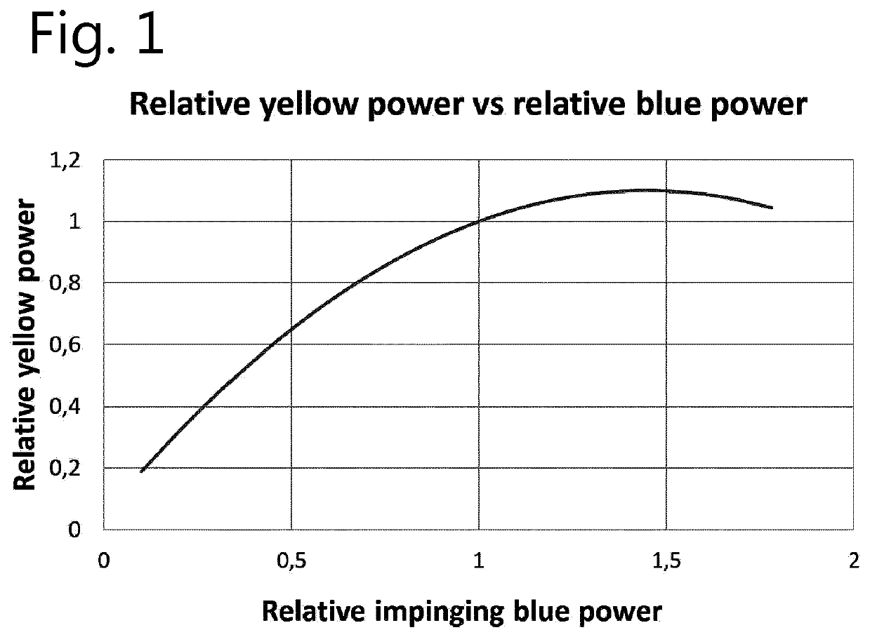
[0236]In a first embodiment according to the present invention, the light source comprises a set of one or more blue lasers and a single wave conversion or “phosphor” element, light from which can be combined into a white light beam, or more generally combined light beam. The light of any or each blue laser can either be emitted directly without wavelength conversion, or it can be partially converted by the wavelength conversion element (“phosphor”), or it can be completely converted by the wavelength conversion element (“phosphor”).

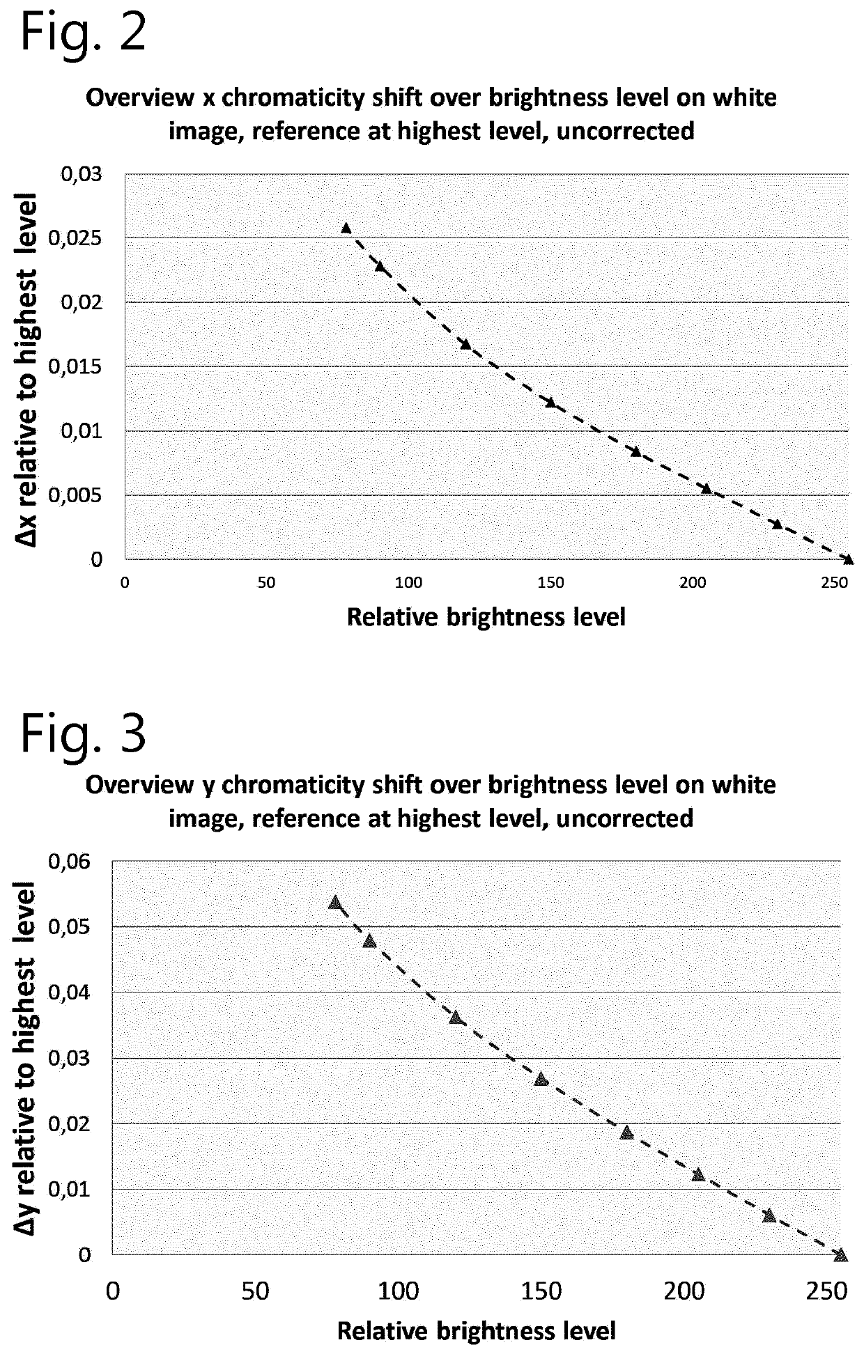
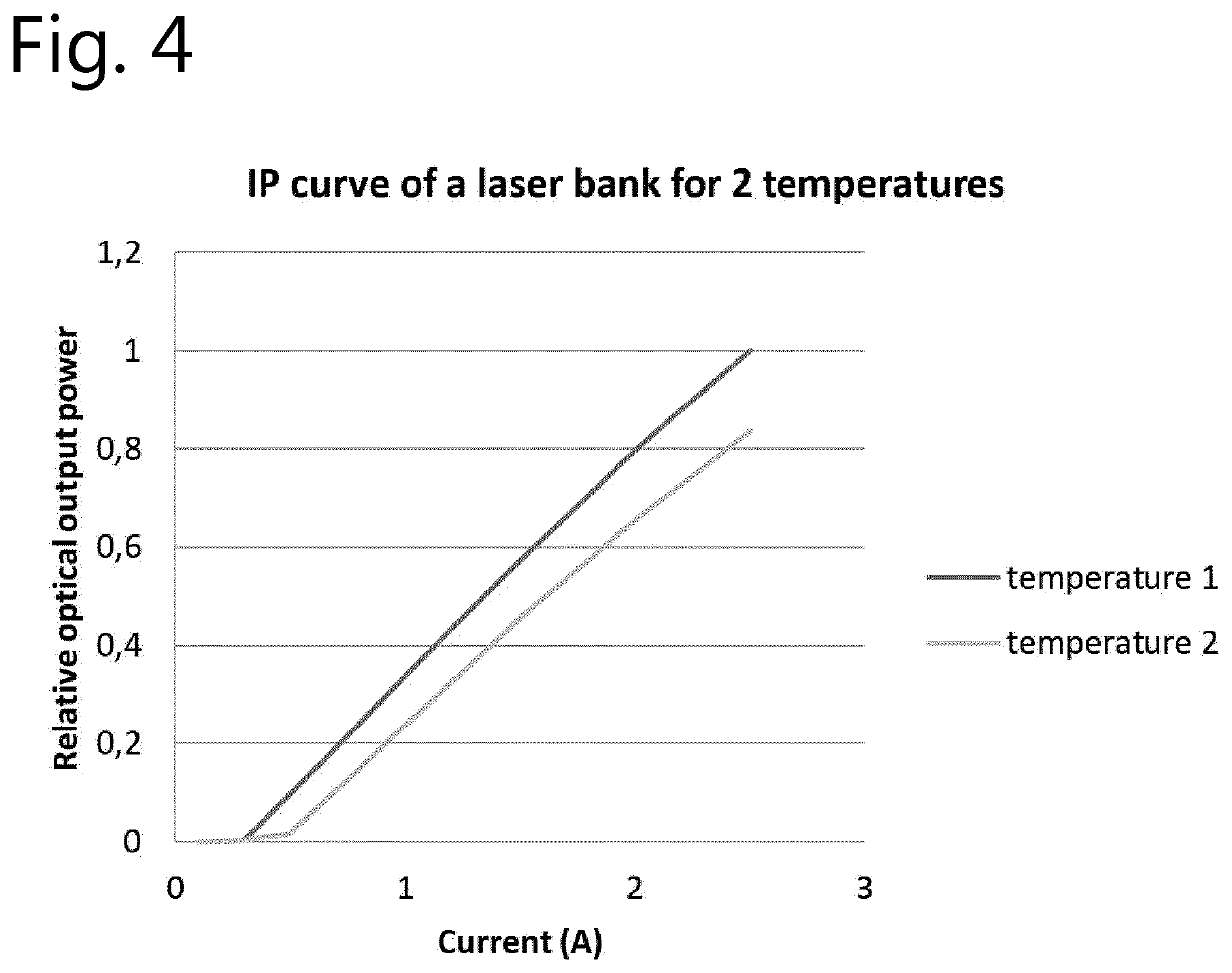
[0237]Embodiments of the present invention can provide a projector, a method or an optical arrangement for use in a projector for calculating the better suited driving current of each laser in the optical design, using a set of optical measurements as input, in order to achieve a desired white point which is constant throughout a dimming range or has a variation which keeps the white point within boundaries, e.g. of the DCI standard.

[0238]Embodiments of ...


PUM

PropertyMeasurementUnit
wavelengthaaaaaaaaaa
colorsaaaaaaaaaa

Abstract

A light projection system and method for generating an image with three primary colors having a module of first blue lasers, second lasers and a wavelength conversion element configured to emit light at a plurality of wavelengths after absorption of a light beam from the second lasers at an excitation wavelength, the output of the module being a combined light beam having a pre-defined chromaticity where the projector is calibrated so as to provide the pre-defined chromaticity of the combined beam over at least a range of laser drive current values to correct for non-linear performance of the wavelength conversion element.

Description

FIELD OF THE INVENTION[0001]The present invention pertains to the field of projectors, and more particularly to the field of projector design and projector calibration, both in the factory and in the field, as well as to projectors and optical arrangements for use in projectors.BACKGROUND[0002]Projection technology has shown an increased interest in the adoption of solid state light sources instead of the conventional technologies such as xenon arc lamps used until now.[0003]An example, of this newer laser technology started in 2010 when Casio unveiled the first mercury-free hybrid laser / LED light source, described as generating over 2000 lumens on a single-chip DLP projector.[0004]Since then many manufacturers have announced their own variation of laser-based solid state projectors and although there are many projection architectures present on the market, the laser-based solid state projectors can be briefly separated in two main categories:[0005]Full laser projectors, e.g. using ...

Claims


Application Information

Patent Timeline
Patent Type & Authority Applications(United States)
IPC IPC(8): G03B21/20H04N9/31
CPCG03B21/2013H04N9/3182H04N9/3158G03B21/2033H04N9/3155G03B21/2053H04N9/3161G03B21/204
Inventor VETSUYPENS, ARNOUTCOULIER, NICO
Owner BARCO NV
Why Eureka
Try Eureka