Optical fiber and optical transmission system
a technology of optical transmission system and optical fiber, applied in the field of optical fiber and optical transmission system, can solve the problems of increasing the load of digital signal processing (dsp) related to mimo, and achieve the effects of low crosstalk, low loss, and low nonlinearity
- Summary
- Abstract
- Description
- Claims
- Application Information
AI Technical Summary
Benefits of technology
Problems solved by technology
Method used
Image
Examples
first embodiment
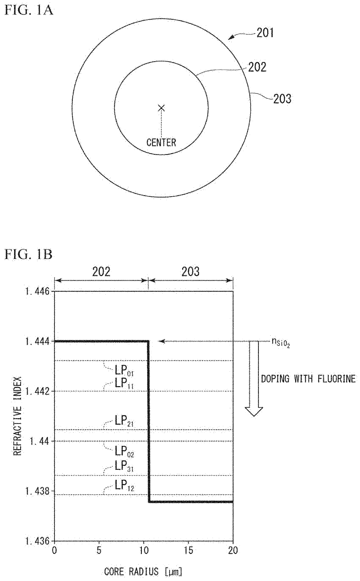
[0055]As shown in FIG. 1A, an optical fiber 201 according to a first embodiment of the present invention includes a core 202, and a cladding 203 that is provided on the outer periphery of the core 202 and has a lower refractive index than the core 202.
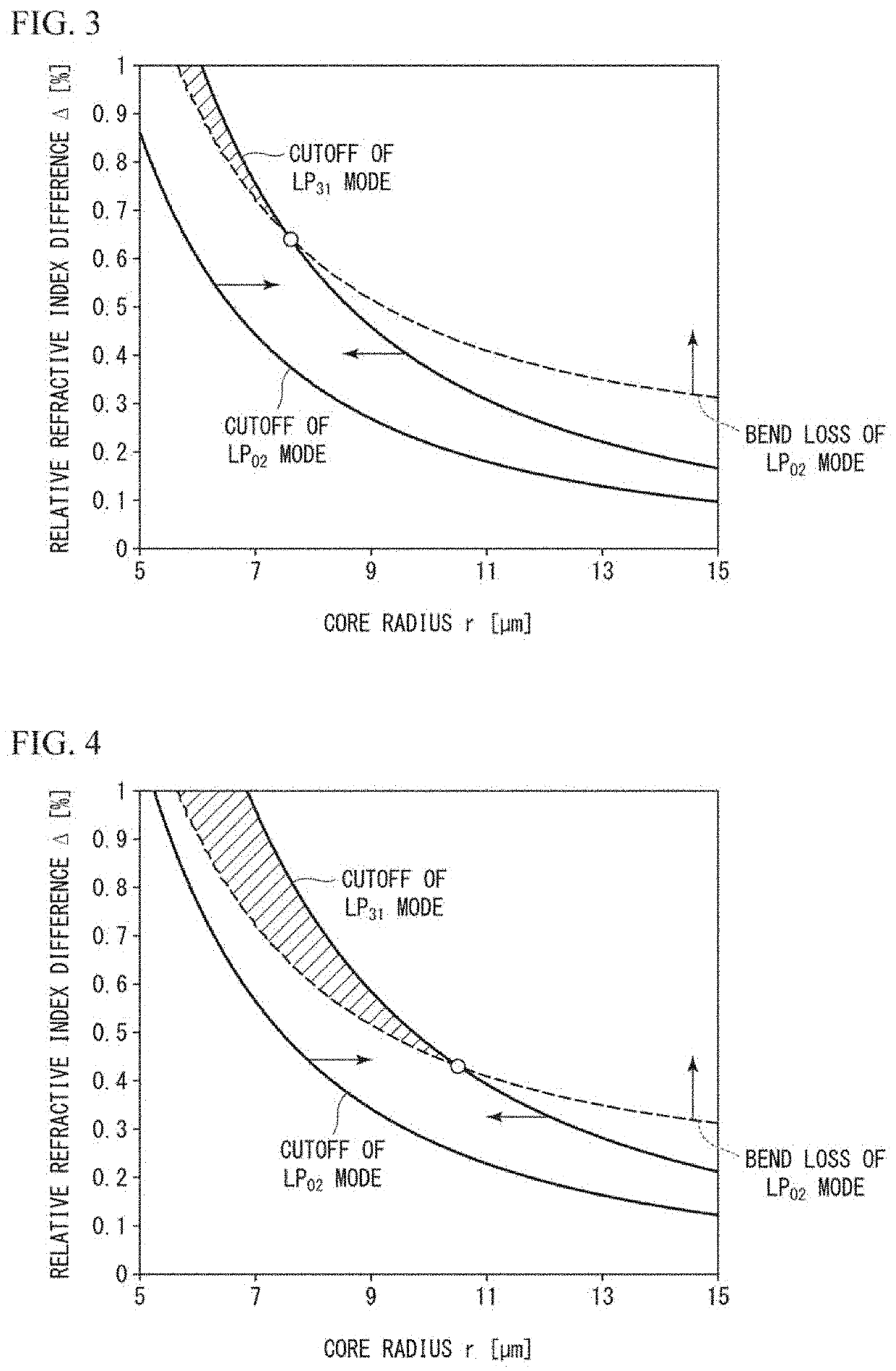
[0056]As shown in FIG. 1B, the optical fiber 201 has a refractive index distribution of step-index-type. Since the optical fiber 201 has the refractive index distribution of step-index-type, the optical fiber 201 can be easily designed and manufactured. The core 202 is made of silica having a purity of 99.999999% or more and an impurity ratio of 10−6% by mass or less. In the present invention, the core radius (radius) r of the core 202 is increased and the relative refractive index difference Δ with respect to the cladding 203 is reduced, as compared with the related art. In the present invention, there are effective refractive indices of the LP31 mode and the LP12 mode theoretically. Since the optical fiber 201 satisfies the bend loss...
second embodiment
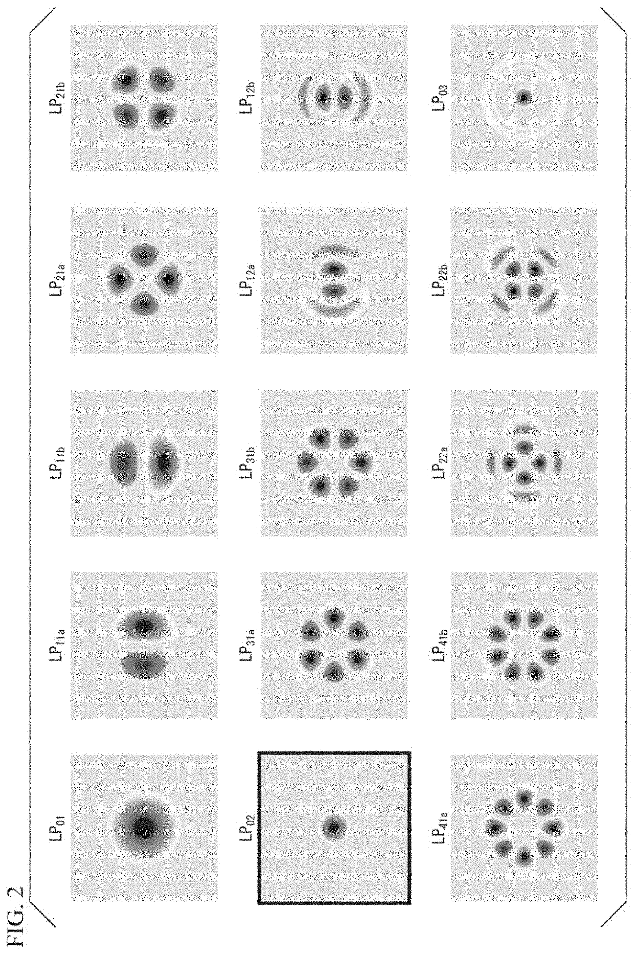
[0077]Next, an optical fiber and an optical transmission system according to a second embodiment will be described. The LP02 mode can reduce crosstalk compared to other modes. When considering the LP03 mode, there is a possibility that crosstalk occurs between the LP31 mode, LP12 mode, LP41 mode, and LP22 mode. Therefore, the LP02 mode is employed in the second embodiment in order to reduce crosstalk.
[0078]Table 1 shows the optical characteristics of eight prototype optical fibers (Spool 1 to 8) when the core radius r is 10.5 μm and the relative refractive index difference Δ is 0.45%.
TABLE 1Fiber lengthAttenuation (dB / km)Aeff (μm2)Spool(km)LP01LP11LP21LP02LP01LP11LP21LP02111.50.1630.1690.1770.175236344373224218.20.1650.1670.171 0.178241348377225322.90.1640.1650.1730.175236343374226425.3 0.1640.1680.1760.179228333364222532.00.1650.1660.179 0.182231335369225625.30.1670.1670.1780.177226329360219731.50.1630.1650.1730.171217311343209838.20.164 0.1680.1790.177227328361220
[0079]The fundame...
third embodiment
[0087]An optical transmission system 401 shown in FIG. 17A includes a receiving part in which a plurality of receivers are connected in parallel. In FIG. 17, the components of the optical transmission system 401 similar to the components of the optical transmission system 301 described above are denoted by the same signs, and the description thereof is omitted. In addition to the configuration of the optical transmission system 301, the optical transmission system 401 further includes an optical amplifier (first amplifier) 405 that is configured to amplify the signal light excited to the LP02 mode.
[0088]In the optical transmission system 401, a signal is encoded on the light of the LP02 mode using a mode exciter for the LP02 mode. Using an optical amplifier capable of amplifying the light of the LP02 mode, the intensity of the light of the LP02 mode is amplified. ASE noise of modes other than the LP02 mode is generated from the optical amplifier generates. Therefore, light of modes ...
PUM
| Property | Measurement | Unit |
|---|---|---|
| effective area | aaaaa | aaaaa |
| radius | aaaaa | aaaaa |
| propagation distance | aaaaa | aaaaa |
Abstract
Description
Claims
Application Information
 - R&D
- Intellectual Property
- Life Sciences
- Materials
- Tech Scout
- Unparalleled Data Quality
- Higher Quality Content
- 60% Fewer Hallucinations
Browse by: Latest US Patents, China's latest patents, Technical Efficacy Thesaurus, Application Domain, Technology Topic, Popular Technical Reports.
© 2025 PatSnap. All rights reserved.Legal|Privacy policy|Modern Slavery Act Transparency Statement|Sitemap|About US| Contact US: help@patsnap.com


