Optical fiber cable
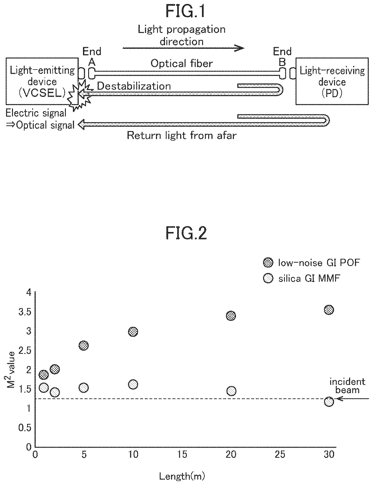
a technology of optical fiber and fiber optic cables, applied in the direction of optical fiber with graded refractive index core/cladding, optical waveguide light guide, instruments, etc., can solve the problems of destabilization of light-emitting devices, the attempt to solve the return light-based problem,
- Summary
- Abstract
- Description
- Claims
- Application Information
AI Technical Summary
Benefits of technology
Problems solved by technology
Method used
Image

Examples
synthesis example b
[Synthesis Example B] Synthesis of Partially Chlorinated Material (see JP 5419815B)
[0058]A production method for the partially chlorinated material will be briefly described below. Trichloroethyl methacrylate preliminarily purified by distillation, cyclohexylmaleimide preliminarily purified by sublimation, and diphenyl sulfide which is a dopant serving as a refractive index imparting agent were subjected to precise weight measurement, individually, and put in a glass container. Further, di-tert-butylperoxide serving as the polymerization initiator and n-laurylmercaptan serving as the chain transfer agent were added such that respective concentrations thereof become given values with respect to the total weight. After sufficiently mixing the mixture, the resulting solution was passed through and filtered by a membrane filter having a given pore size, and the filtered solution was put in a glass polymerization container. Subsequently, while argon gas is introducing into the glass poly...
synthesis example 1
Synthesis Method for POF Material using Partially Fluorinated Material
[0082]A core rod and a hollow-structured cladding rod were separately produced, and then the hollow-structured cladding rod was inserted over the outer periphery of the core rod to produce a preform.
[0083]In production of the core rod, firstly, hexafluoroisopropyl α-fluoroacrylate as a partially fluorinated derivative of methyl methacrylate was used as a monomer material. This material is liquid at normal temperature. 10 g of the material was filled in a vial tube having an inner diameter of 5 cm and a length of 7 cm. Further, each of a dopant, a polymerization initiator and a chain transfer agent was added in a required amount. The amounts of the dopant, the polymerization initiator and the chain transfer agent were set, respectively, to 8.0 mol %, 0.1 mol % and 0.1 mol %. A material used as the dopant was decaflourobipheny. Tert-butyl peroxy-2-ethylhexanoate was used as the polymerization initiator, and butyl me...
synthesis example 2
Synthesis Method for Perfluorinated Material
[0086]139 g of a mixture of 2-chloro-1-propanol, 1-chloro-2-propanol and methyl trifluoropyruvate was put in a flask, and methyl trifluoropyruvate was added thereto to obtain 230 g of a purified product of 2-carbomethyl-2-trifluoromethyl-4-methyl-1,3 -dioxolane. Subsequently, fluorination of perfluoro-4-methyl-2-methylene-1,3-dioxolane was performed. Specifically, under the condition that 1,1,2-trichlorotrifluoroethane was used as a solvent, and nitrogen gas and fluorine gas was supplied to a reaction container, respectively, at a constant flow rate of 1340 cc / min and at a constant flow rate of 580 cc / min, 230 g of the previously-prepared 2-carbomethyl-2-trifluoromethyl-4-methyl-1,3 -dioxolane was slowly added to the reaction container in a nitrogen-fluorine atmosphere, so as to be subjected to fluorination treatment to obtain 150 g of perfluoro-2,4-dimethyl-1,3-dioxolane-2-carboxylic acid. A fluorination yield in this step was about 85%. ...
PUM
| Property | Measurement | Unit |
|---|---|---|
| length | aaaaa | aaaaa |
| correlation length | aaaaa | aaaaa |
| inertial radius | aaaaa | aaaaa |
Abstract
Description
Claims
Application Information
 - R&D
- Intellectual Property
- Life Sciences
- Materials
- Tech Scout
- Unparalleled Data Quality
- Higher Quality Content
- 60% Fewer Hallucinations
Browse by: Latest US Patents, China's latest patents, Technical Efficacy Thesaurus, Application Domain, Technology Topic, Popular Technical Reports.
© 2025 PatSnap. All rights reserved.Legal|Privacy policy|Modern Slavery Act Transparency Statement|Sitemap|About US| Contact US: help@patsnap.com