A compact heat recovery ventilation system

a ventilation system and heat recovery technology, applied in ventilation systems, lighting and heating apparatuses, heating types, etc., can solve the problems of high sound level, contribute to the pressure drop of ventilation systems, and major problems of modern ventilation systems, and achieve the effect of easy integration

Inactive Publication Date: 2020-09-24
INDAL DESIGN LAB
View PDF4 Cites 5 Cited by
  • Summary
  • Abstract
  • Description
  • Claims
  • Application Information

AI Technical Summary

Benefits of technology

The invention is a compact and flat air handling system. Its main benefit is that it allows for the addition of any air handling unit with the same thickness and width as the system without compromising its aesthetics or design. This makes the system more flexible and allows for additional design options.

Problems solved by technology

All these processes and systems (countercurrent, cross-current or in-line) restrict the airflow and contribute to the pressure drop of the ventilation system.
Ambient pressure fluctuations due to weather or movement of an enclosure is another source of the pressure load that requires additional power consumption for ventilation system.
However, higher power often results in higher sound level, which is one of the reasons why more powerful systems are centralized with long bulky ducts and noisy blowers that need to be closed off in a sound insulated enclosure.
This brings up one of the major problems for modern ventilation systems.
The powerful ventilation systems are often too bulky, and the small ones are often not powerful enough.
Other disadvantages of the smaller systems of lower functionality are that most designs are difficult to conceal, the small size results in higher motor and blower inefficiency and, as they are closer to the user, their noise level can still be a nuisance.
This dilemma causes a problem, specifically in projects, where there is only limited space available for the ventilation system, for instance, when older apartments or buildings are being renovated.
In these very common cases, there are often simply no good solutions possible.
Most of the current Heat Recovery Systems have traditional axial fans, which are often used as air moving devices, have certain limitations because they are not suited to create high static pressure at given airflow when various air processing units are added (heat exchanger, filter etc.) and when affected by ambient pressure fluctuations (e.g., wind loads, vacuum pressure inside the building envelope).
This leaves little room for any noise mitigation, like a silencer, unless by compromising the flat design.
However electric motors for typical crossflow blowers are located adjacent to the impellers, because if a conventional electric motor is placed inside the impeller, it greatly affects the internal aerodynamic structure of the crossflow blower, thus dramatically decreasing performance characteristics.
Heat exchange takes place through the radial fins and the partition itself, but as the flow is co-current, the efficiency is limited.
The countercurrent fix of the otherwise co-current system has some disadvantages that may limit its use.
The heat exchanger relies on using copper wire, resulting in higher cost and low pressure drop over the heat exchanger may cause higher sensitivity to pressure fluctuations.
However, all known designs do not provide a thin air processing device with the crossflow blower for such wall-mounted air movement systems.
Such solutions are thicker than desired and they do not meet the market requirements.
There is a main problem for all known air processing-heat exchanger devices where they cannot resolve the contradiction between the high performance that requires a relatively large impeller diameter on one hand and a small thickness of the whole device on the other hand.
There is, however, too little space for air processing units, and blower inside these slabs.
All these prior art designs still have some disadvantages that limited abilities to create flat compact heat recovery system capable to be soundless, wall-mounted or even fit inside of the wall or ceiling.

Method used


Image

  • A compact heat recovery ventilation system
  • A compact heat recovery ventilation system
  • A compact heat recovery ventilation system

Examples


Embodiment Construction

[0071]Preferred embodiment of the present invention will be described in detail below with reference to the accompanying drawings.

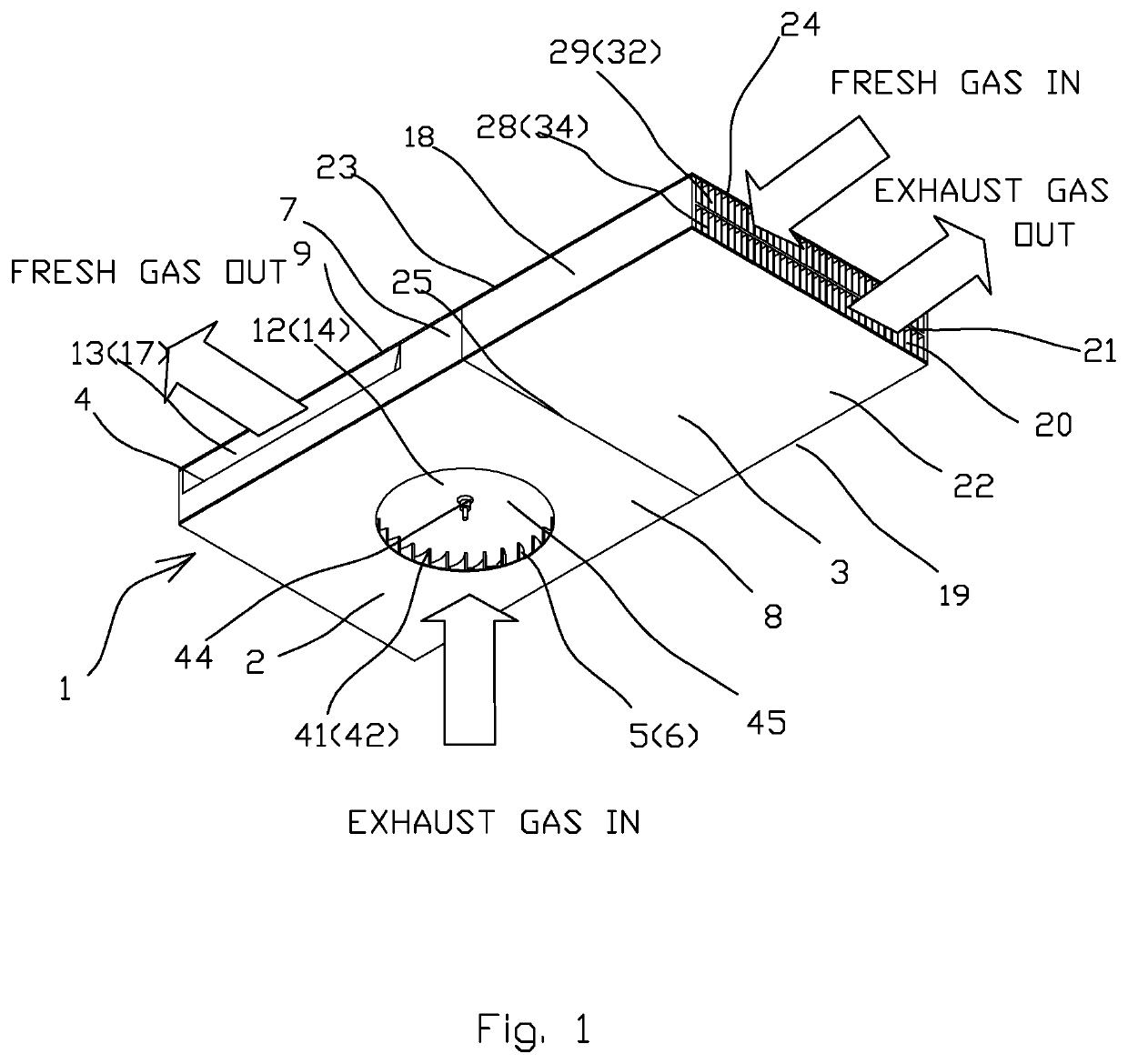
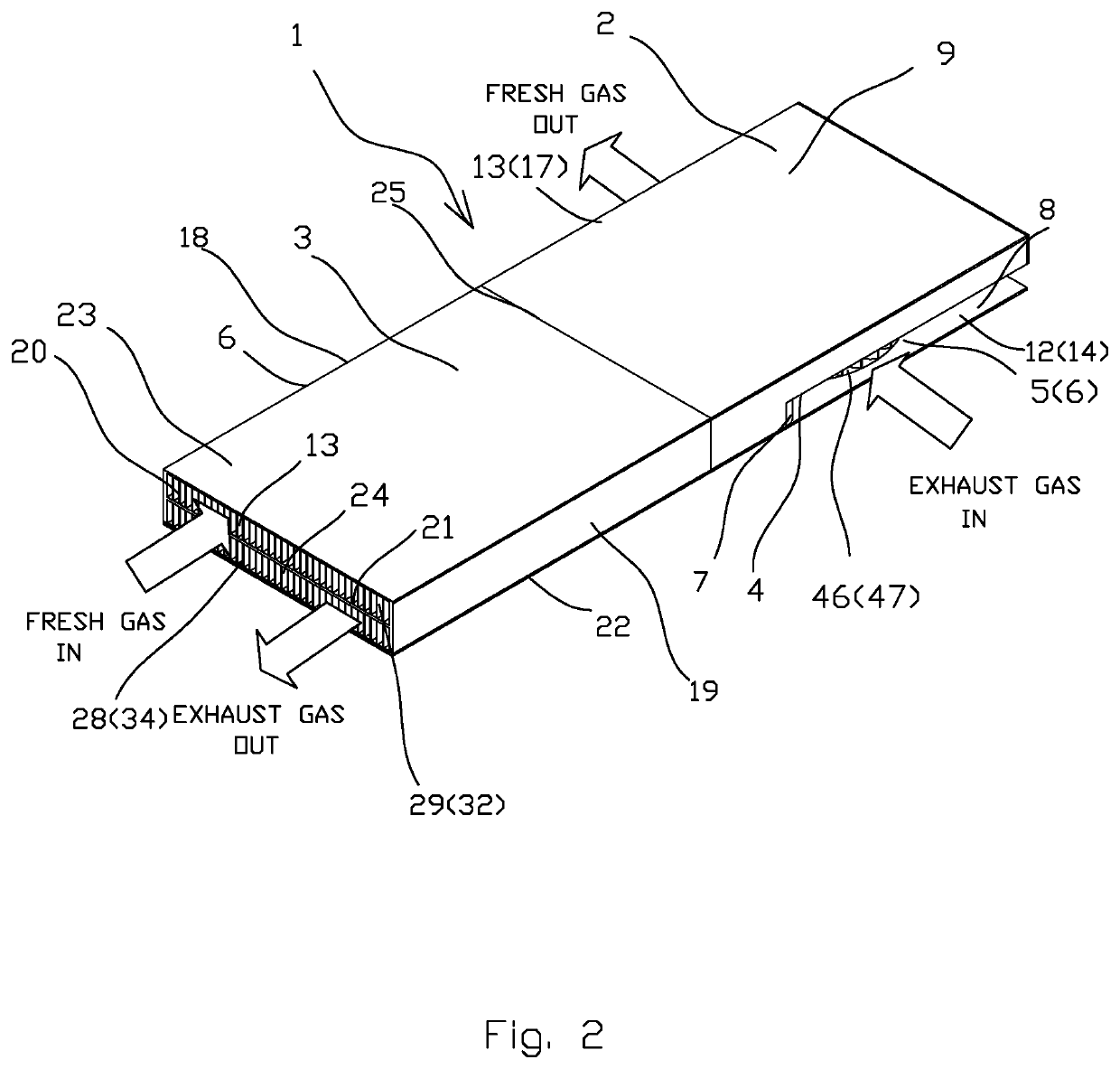
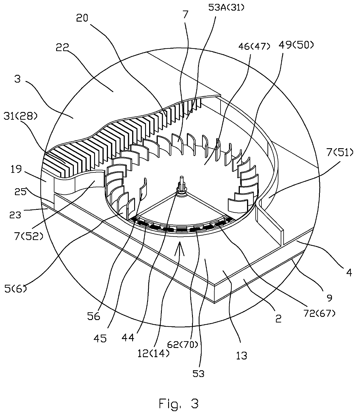
[0072]A compact heat recovery system 1 (FIGS. 1-23) comprises air module assembly 2 and heat exchanger assembly 3. Air module assembly 2 includes base plate 4, two radial blowers 5 and 6 airflow guides 7, two side panels 8 and 9. The base plate 4 located between radial blower 5 and 6, divides the airflow in two hydraulically isolated canals, exhaust gas canal 12 and fresh gas canal 13 with exhaust gas inlet 14, fresh gas inlet 15 and exhaust gas outlet 16, fresh gas outlet 17.

[0073]The heat exchanger assembly 3 comprises of heat exchanging elements 20, center plate 21 fixed with outside panels 22 and 23 and withe with heat exchanger sides 18 and 19. The center plate 21 divides openings of the ends 24, 25 of the heat exchanger assembly 3 for two hydraulically isolated flow conduits 28 and 29 with exhaust gas intake 31, fresh gas intake 32 and exhaust gas o...


PUM


Abstract

A countercurrent heat recovery ventilation system includes an air module assembly and heat exchanger assembly. Air module assembly made from front and back panels connected by two side panels, base plate fixed with the side panels and placed parallel between side panels and a double side radial impeller with a shaft, an electric drive form two hydraulically isolated flow canals with inlet and outlet openings.The heat exchanger assembly comprises a heat-exchanger that could be done as changeable flow side heat-exchanger made as folded corrugated fins or plates, thus each of the both flow passages split in separate flow channels. Every other channel is sealed to flow from flow same direction forcing the flow to be in opposite direction in all adjacent cannels. This forms two hydraulically isolated flow passages with intake and outtake openings connected respectively with outlet and inlet openings of the air blower assembly.

Description

[0001]The present application claims the benefit of priority of U.S. Provisional Patent Application No. 62 / 316,325, filed Mar. 31, 2016 the entire context of which is incorporated herein by reference.FIELD OF THE INVENTION[0002]The present invention relates generally to heat ventilation and air conditioning (HVAC) systems for moving air, and / or regulating the temperature, humidity, chemistry and quality of indoor air. More particularly, the present invention relates to air processing devices such as ventilators, including heat ventilators, coolers, air conditioners humidifiers and air purifiers. The present invention is particularly, but not exclusively, useful for systems that are mounted inside a wall or ceiling and constitute a part of room decor; therefore, thickness of the system is a critical factor. Another critical factor is the countercurrent air flow (air flowing in opposite directions) that provides the highest energy recovery efficiency or chemical recovery efficiency. T...

Claims


Application Information

Patent Timeline
IPC IPC(8): F24F12/00F04D25/06F04D25/08F04D25/16
CPCF04D25/08F24F12/006F04D25/06F04D25/16F24F13/20B60H1/00321F04D17/04F04D17/16F04D25/163F04D29/4226B60H1/039F24F2221/17F24F2221/14Y02B30/56B60H1/00335F24F1/00F28D21/0014
Inventor LOPATINSKY, EDWARDSCHAEFER, DANIELJOHANNES, LOFTSSON
Owner INDAL DESIGN LAB
Why Eureka
Try Eureka