

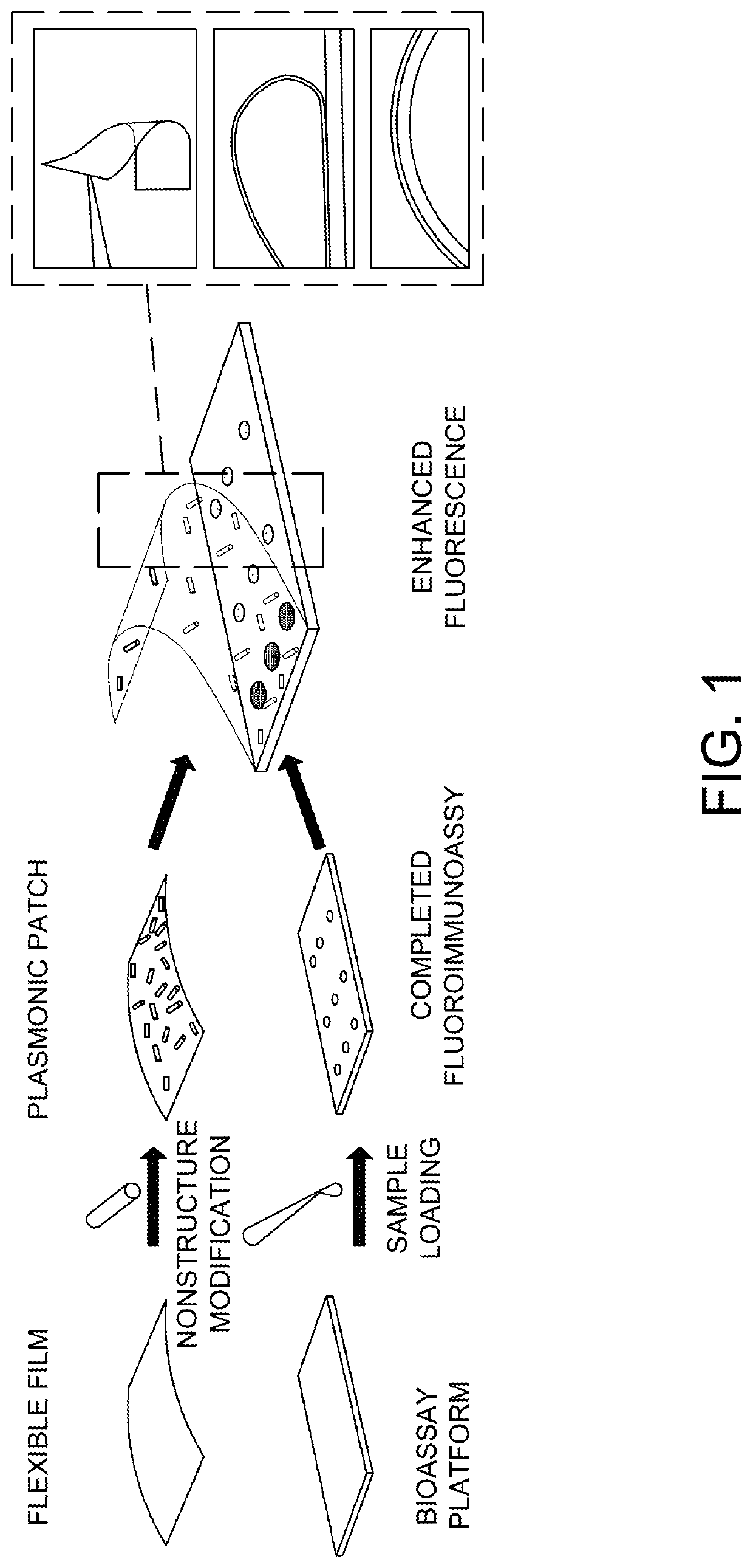
Plasmonic patch as a universal fluorescence enhancer
a plasmonic patch and fluorescence enhancer technology, applied in the field of new plasmonic patches, can solve the problems of not being easily applied to a large variety of systems or bioassays, affecting the fluorescence quality of the sample, so as to improve the fluorescence quality, enhance the fluorescent signal, and enhance the fluorescent signal
- Summary
- Abstract
- Description
- Claims
- Application Information
AI Technical Summary
Benefits of technology
Problems solved by technology
Method used
Image

Examples
examples
[0086]Preparation of the Plasmonic patch
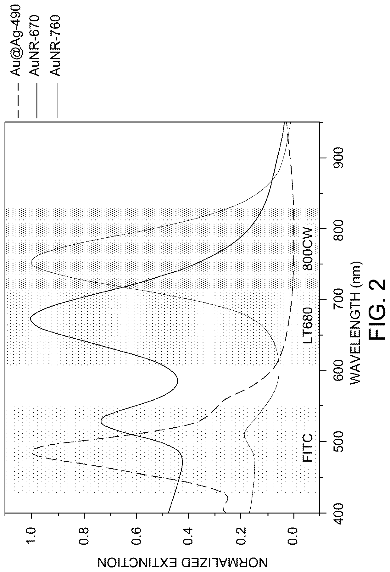
[0087]Synthesis of Au@Ag-490. To synthesize Ag nanocubes, Au nanospheres with a diameter of 30 nm were employed as the seed. The 30 nm Au nanospheres were in turn synthesized by a seed-mediated method. First, Au seeds were synthesized by adding 0.6 mL of ice-cold NaBH4 solution (10 mM) into a solution containing 0.25 mL HAuC14 (10 mM) and 9.75 mL CTAB (0.1 M) under vigorous stirring at room temperature for 10 min. The solution color changed from yellow to brown indicating the formation of Au seed. Next, 0.25 mL of the seed solution was added to a growth solution containing 10 mL of CTAC (cetyltrimethylammonium chloride, 0.2 M) and 7.5 mL of ascorbic acid (0.1 M) under stirring. HAuC14 (10 mL, 0.5 mM) was added to the growth solution as a single addition, resulting in the formation of Au nanospheres with a diameter of 10 nm. The 10 nm Au nanospheres were centrifuged at 13,000 rpm for 30 minutes. For further growth of Au nanoparticles to a diame...
PUM
| Property | Measurement | Unit |
|---|---|---|
| thickness | aaaaa | aaaaa |
| diameter | aaaaa | aaaaa |
| diameter | aaaaa | aaaaa |
Abstract
Description
Claims
Application Information