
Capacitive micro-machined ultrasound transducer (CMUT) devices

a micro-machined, ultrasonic technology, applied in the field of ultrasonic transducer probes, can solve the problems of increasing the complexity of providing bias voltage to all of the cells in the probe, and affecting the operation of the entire transducer probe. achieve the effect of simplifying the differential implementation

Active Publication Date: 2020-11-05
KONINKLJIJKE PHILIPS NV
View PDF0 Cites 6 Cited by
  • Summary
  • Abstract
  • Description
  • Claims
  • Application Information

AI Technical Summary

Benefits of technology

This patent describes a system that prevents damage to a CMUT transducer by using a buffer element to prevent short circuits. The system also uses an intermediate circuit to connect the transducer elements to the driving and sensing electronics. The design of the intermediate circuit optimizes its production. Additionally, the patent describes a differential driving system that provides a simpler and more efficient solution for driving the transducer. The decoupling of the bias voltage allowed by the intermediate circuit allows for separated driving and receiving electronics, and avoids the need for a transmit-receive switch. Overall, the patent provides a solution for protecting CMUT transducers and optimizing their performance.

Problems solved by technology

While such an architecture has numerous performance advantages as described above, a problem arises in that the failure of a single MUT cell can render a vast number of cells inoperative.
While the failure of a single cell by itself may not appreciably affect the performance of the transducer probe, the shorting out of a large number of other cells can render the entire transducer probe inoperative.
There are several drawbacks to this approach, however.
One is that each row or column of interconnected cells must be separately biased, increasing the complexity of providing bias voltages to all of the cells in the probe.
Another is that a fuse occupies a relatively large area on the MUT substrate, decreasing the area on the substrate available for MUT cells and hence the sensitivity of the transducers.
Yet another is that a plurality of cells are removed from operation in the probe, the failed cell as well as the others to which it is connected, which also degrades the performance of the ultrasound probe.

Method used


Image

  • Capacitive micro-machined ultrasound transducer (CMUT) devices
  • Capacitive micro-machined ultrasound transducer (CMUT) devices
  • Capacitive micro-machined ultrasound transducer (CMUT) devices

Examples


Embodiment Construction

[0057]It should be understood that the Figures are merely schematic and are not drawn to scale. It should also be understood that the same reference numerals are used throughout the Figures to indicate the same or similar parts.

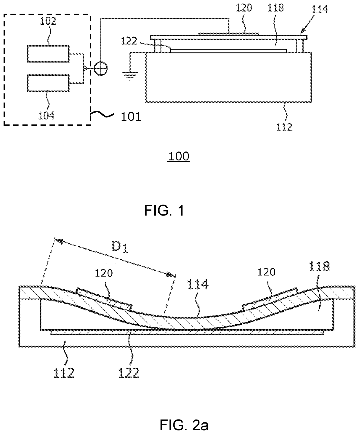
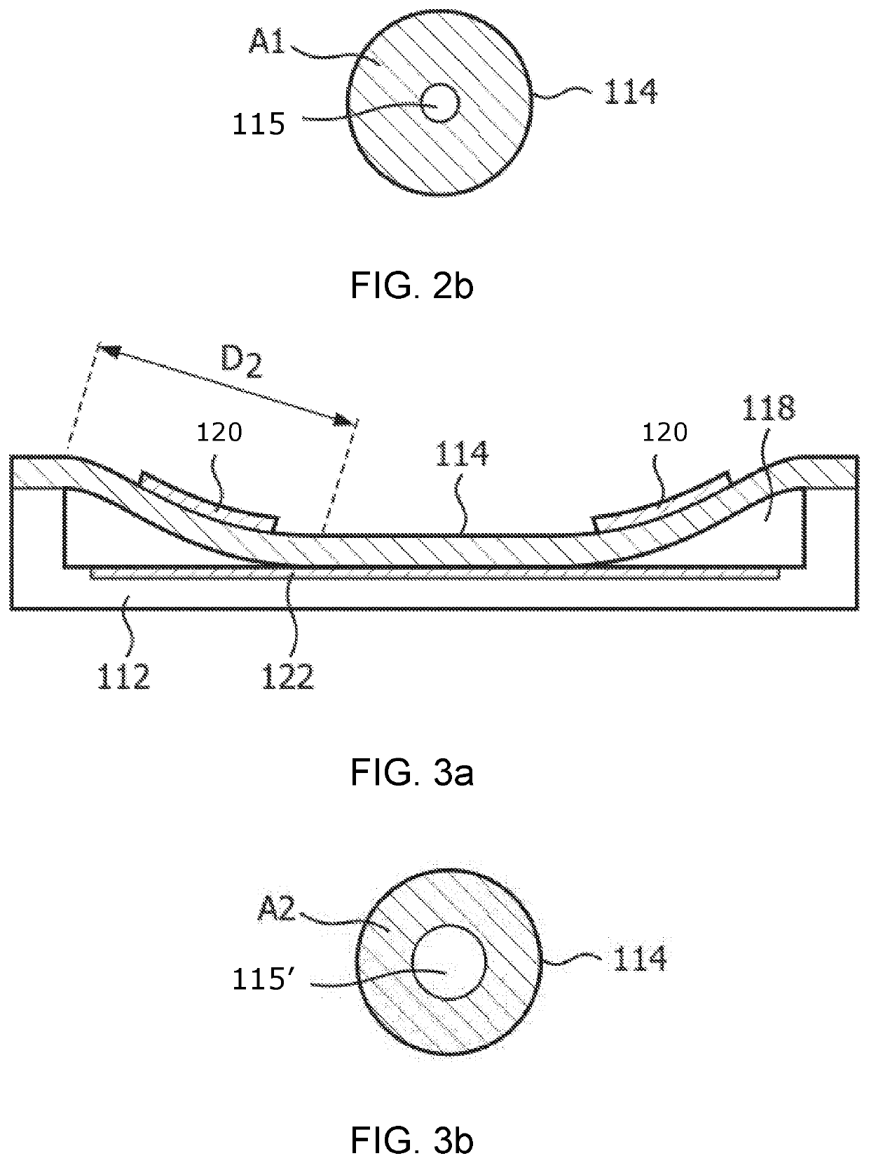
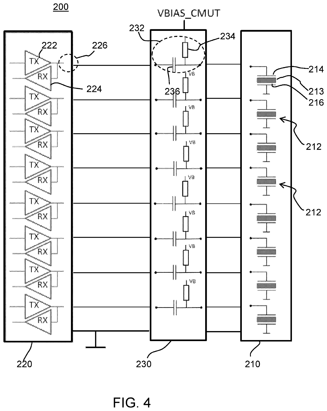
[0058]The invention provides an ultrasound system comprising a set of CMUT ultrasound transducer devices and a drive circuit for operating the ultrasound transducer devices, for delivering an AC drive signal and receiving a reflected signal. An intermediate circuit is between the drive circuit and the set of ultrasound devices in the form of an array of coupling circuits, each coupling circuit between the drive circuit and an associated at least one ultrasound transducer device. Each coupling circuit comprises a buffer element (preferably a resistor) connected between a bias voltage and a device terminal and a series capacitor, and is formed as a passive integrated technology circuit. The intermediate circuit serves as a connection link between the set of CMU...


PUM


Abstract

An ultrasound system has a set of CMUT ultrasound transducer devices and a drive circuit for operating the ultrasound transducer devices, for delivering an AC drive signal and receiving a reflected signal. An intermediate circuit is between the drive circuit and the set of ultrasound devices in the form of an array of coupling circuits, each coupling circuit between the drive circuit and an associated at least one ultrasound transducer device. Each coupling circuit comprises a buffer element connected between a bias voltage and a device terminal and as series capacitor. The intermediate circuit serves as a connection link between the set of CMUT transducer elements and the driving / sensing electronics, and is formed as a passive integrated technology circuit. The buffer element prevents a low-impedance short between the CMUT cell bias node and the counter electrode in the case of a CMUT cell drum short circuit. In this way, failure of an individual cell will not cause a breakdown of the whole CMUT array nor a breakdown of the driving electronics.

Description

RELATED APPLICATION[0001]This application claims priority to and the benefit of European Application Serial No. 19171719.8, filed Apr. 30, 2019. This application is incorporated by reference herein in its entirety.FIELD OF THE INVENTION[0002]This invention relates to ultrasonic transducer probes which use capacitive micromachined ultrasonic transducers (CMUTs), for example for medical diagnostic ultrasonic imaging.BACKGROUND OF THE INVENTION[0003]Ultrasonic transducers used for medical imaging have numerous characteristics that lead to the production of high quality diagnostic images.[0004]Traditionally, piezoelectric materials have been used for ultrasonic transducers. Examples are lead zirconate titanate (PZT) and polyvinylidene difluoride (PVDF) materials, with PZT being particularly popular as the material of choice. Single crystal piezoelectric materials are used to achieve high piezoelectric and electro-mechanical coupling constants for high performance transducers.[0005]Recen...

Claims


Application Information

Patent Timeline
Patent Type & Authority Applications(United States)
IPC IPC(8): B06B1/02G01S15/89G01S7/52A61B8/00
CPCB06B1/0292G01S15/8925G01S15/8993A61B8/4494G01S7/52079B06B1/0207G01S7/52046B06B2201/51B06B2201/20
Inventor VAN RENS, ANTONIA CORNELIA
Owner KONINKLJIJKE PHILIPS NV
Learn More