Corrosion- and erosion-resistant coating for turbine blades of gas turbines

US20200392629A1Active Publication Date: 2020-12-17OERLIKON SURFACE SOLUTIONS AG PFAFFIKON

Image

  • Corrosion- and erosion-resistant coating for turbine blades of gas turbines
  • Corrosion- and erosion-resistant coating for turbine blades of gas turbines
  • Corrosion- and erosion-resistant coating for turbine blades of gas turbines

Examples


first embodiment

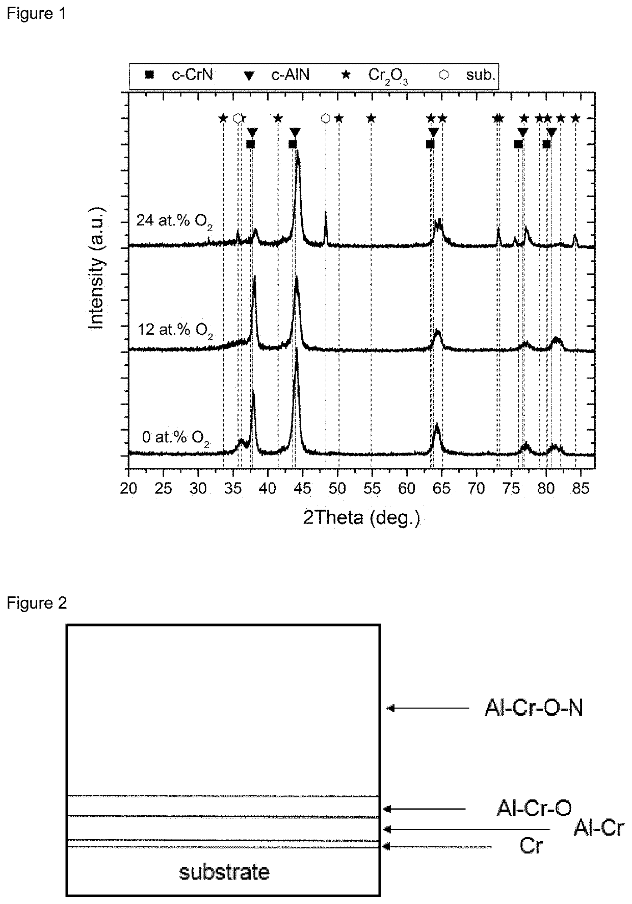
[0041]FIG. 2 schematically shows the layer structure of a first embodiment A of the present invention with the structure: substrates / Cr / AlCr / AlCrO / Al—Cr—O—N, the outermost layer being a monolayer.

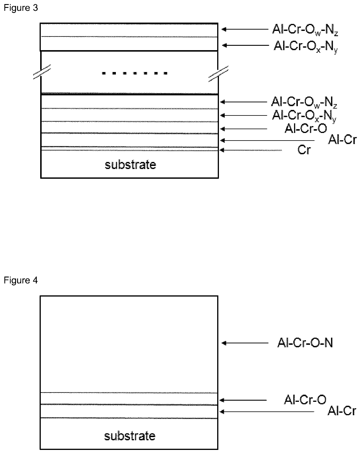
[0042]FIG. 3 schematically shows the layer structure of a second embodiment B of the present invention, with the structure: substrates / Cr / AlCr / AlCrO / Al—Cr—O—N, the outermost layer being a multilayer composed of a plurality of individual layers according to the invention, which together form the outer functional layer.

[0043]FIG. 4 schematically shows the layer structure of a third embodiment C of the present invention with the structure: substrates / AlCr / AlCrO / Al—Cr—O—N, the outermost layer being a monolayer.

third embodiment

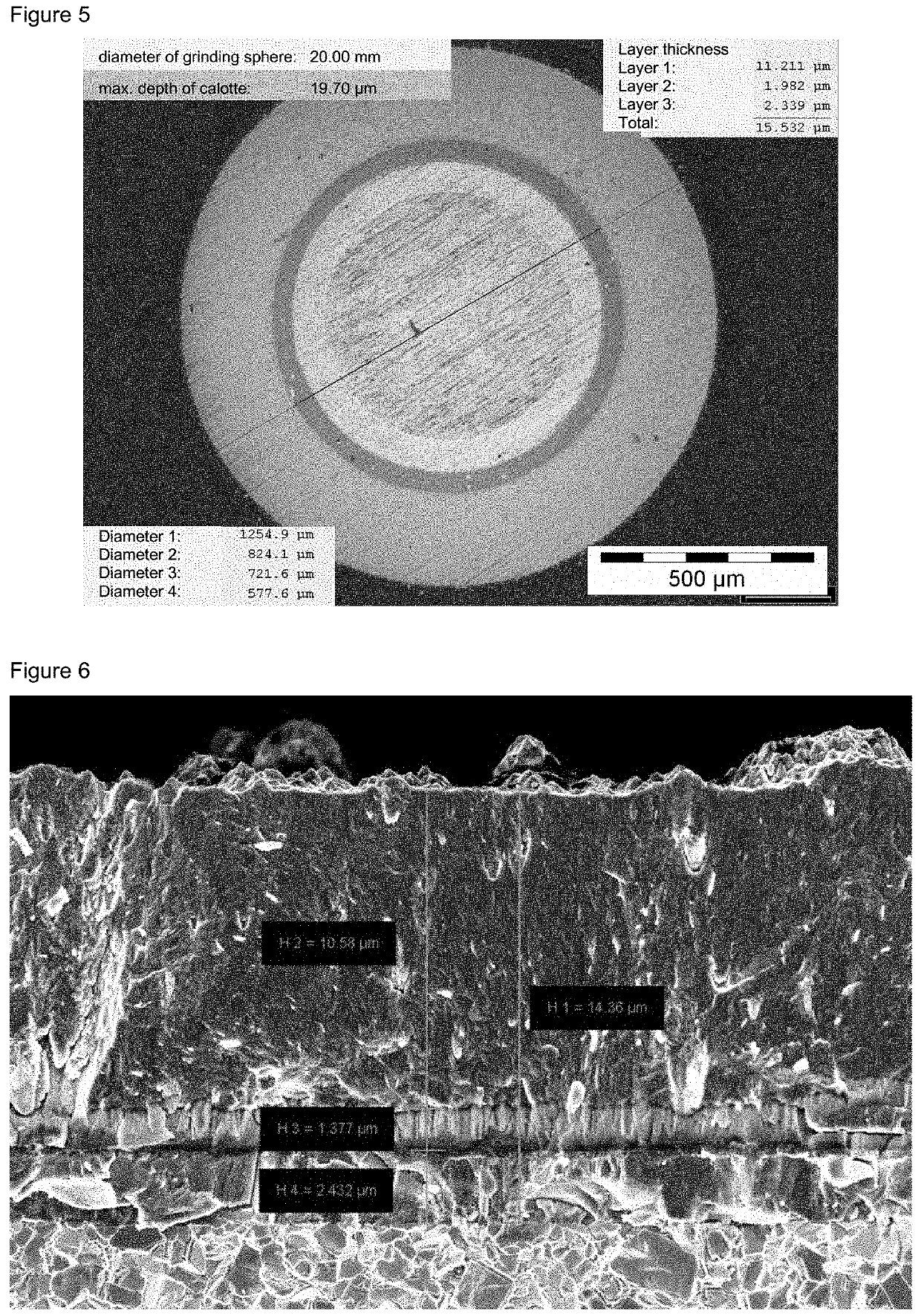
[0044]FIG. 5 shows a calotte grinding of a layer system according to the

[0045]FIG. 6 shows the cross section of a layer system according to the third embodiment in an SEM image.

[0046]FIG. 7 schematically shows the layer structure of a fourth embodiment D of the present invention with the structure: substrates / AlCr / AlCrO / Al—Cr—O—N, the outermost layer being a multilayer.

[0047]FIG. 8 shows the comparison between a conventional component, referred to as TurbinPro and coated with TiAlN, with embodiment C in the salt spray test. TurbinPro is a commercially available coating product from Oerlikon Surface Solutions AG, Switzerland.

[0048]FIG. 9a shows the resistance to solid-state erosion for a particle incidence angle of 90° for different surfaces.

[0049]FIG. 9b shows the resistance to solid-state erosion for a particle incidence angle of 20° for different surfaces.

[0050]FIG. 10 shows the chemical composition of an example of a layer system according to the invention.

[0051]The layer system ...


PUM

PropertyMeasurementUnit
Pressureaaaaaaaaaa
Pressureaaaaaaaaaa
Thicknessaaaaaaaaaa

Abstract

A component of a turbine, in particular a gas turbine, wherein the component has a coating for increasing the erosion and corrosion resistance, wherein the coating is preferably applied directly to the component, wherein the coating consists of a functional layer and an intermediate layer, wherein the intermediate layer is arranged between the turbine blade substrate and the functional layer and wherein the functional layer consists of the elements Al, Cr, O and N.

Description

[0001]The present invention relates to blades for gas turbines with a coating having improved erosion and corrosion resistance and to other components of gas turbines with such a coating.TECHNICAL BACKGROUND[0002]Components of gas turbines are exposed to a corrosive medium. It is known to apply coatings to protect these components from corrosion. Among other things, physical coatings that have been deposited from the gas phase are used here.[0003]According to conventional prior art, TiN / Ti, TiN / TiAlN and TiAlN layer systems are used. These show improved erosion resistance, but inadequate corrosion resistance, for example, in applications on high-chromium steel substrates.[0004]DE102015212588 represents a further development. It describes a coating system for a corrosively stressed substrate with a surface comprising at least a first, second and third layer, in which[0005]the first layer arranged between the surface of the substrate and the second layer is designed as an adhesion pro...

Claims


Application Information

Patent Timeline
17 Dec 2020
Publication
US20200392629A1
IPC
C23C28/04; C23C14/06; C23C28/00
CPC
C23C14/0676; C23C28/345; C23C28/042; C23C28/321; C23C30/00; C23C28/30; C23C28/34; C23C28/32
Inventors
RAMM, JUERGEN; BOLVARDI, HAMID