Phase Change Material for Heat Exchange Fluid/Coolant

Pending Publication Date: 2021-02-25
CASTROL LTD
View PDF0 Cites 3 Cited by
  • Summary
  • Abstract
  • Description
  • Claims
  • Application Information

AI Technical Summary

Benefits of technology

[0005]Although phase change material coolants are promising, there are two key drawbacks that may prevent their use in coolant systems. First, coalescence of molten paraffin presents a major drawback for its use as phase change material coolant. Specifically, the coalescence of molten paraffin results in deposition of solid paraffin in the cooling system and eventual blockage of the cooling system. Next, the dispersed paraffin particles increase the viscosity of the fluid. In general, the viscosity o

Problems solved by technology

Although phase change material coolants are promising, there are two key drawbacks that may prevent their use in coolant systems.
First, coalescence of molten paraffin presents a major drawback for its use as phase change material coolant.
Specifically, the coale

Method used


Image

  • Phase Change Material for Heat Exchange Fluid/Coolant
  • Phase Change Material for Heat Exchange Fluid/Coolant
  • Phase Change Material for Heat Exchange Fluid/Coolant

Examples


example 1

[0100]The emulsion of the disclosure was prepared by using the above-noted methods. Specifically, 53.9 wt % paraffin wax (Sasolwax, available from Sasol), with a melting point of 64° C., 6.9 wt % emulsifier (Wax Emulsifier 2106 avaialble from Clariant), and 6.9 wt % glycerol were combined in 32.3 wt % water and emulsified. After emulsification, the resultant micelles were analyzed using a Beckman Coulter Laser Diffraction PS Analyzer (LS 13 320) The mean particle size of the micelles in the emulsion was determined to be 0.510 μm, the median particle size was 0.505 μm and the mode particle size was 0.520 μm, with fewer than 10% of particles having a mean diameter of less than 0.415 μm or greater than 0.617 μm.

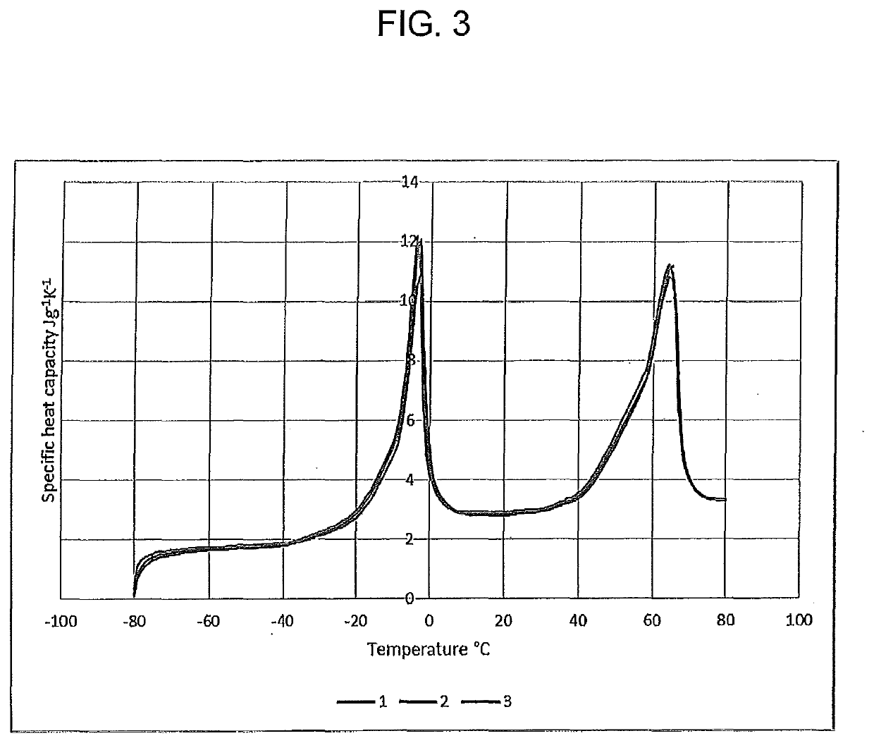
[0101]FIG. 3 shows the variation of the specific heat capacity of the obtained emulsion from −80° C. to +80° C.; the data of FIG. 3 is also presented in Table 1 below. A spike in heat capacity around 12 J / gK is due to ice from the continuous water phase melting at −8.4° C. (note...

embodiment 1

2. The emulsion of embodiment 1, wherein the micellar size distribution d10 is no less than 50% of d50 and d90 is no more than 150% of d50, or d10 is no less than 60% of d50 and d90 is no more than 140% of d50, or d10 is no less than 70% of d50 and d90 is no more than 130% of d50, or d10 is no less than 75% of d50 and d90 is no more than 125% of d50, or d10 is no less than 80% of d50 and d90 is no more than 120% of d50.

embodiment 2

3. The emulsion of embodiment 2, wherein d50 is in the range of 0.1 μm to 1.5 μm; e.g., 0.1 μm to 1.2 μm, or 0.1 μm to 1.0 μm, or 0.1 μm to 0.5 μm, or 0.1 μm to 0.4 μm, or 0.2 μm to 1 μm, or 0.2 μm to 0.8 μm, or 0.2 μm to 0.6 μm, or 0.2 μm to 0.5 μm, or 0.2 μm to 0.4 μm, or 0.4 μm to 1 μm, or 0.4 μm to 0.8 μm, or 0.4 μm to 0.6 μm, or 0.4 μm to 0.5 μm, or 0.3 μm to 0.5 μm, or 0.35 μm to 0.45 μm.

4. The emulsion of embodiment 1 or 2, wherein the micelles have a mean diameter in the range 0.1 μm to 1 μm; e.g., about 0.1 μm to about 0.8 μm, or about 0.1 μm to about 0.6 μm, or about 0.1 μm to about 0.5 μm, or about 0.1 μm to about 0.4 μm, or about 0.2 μm to about 1 μm, or about 0.2 μm to about 0.8 μm, or about 0.2 μm to about 0.6 μm, or about 0.2 μm to about 0.5 μm, or about 0.2 μm to about 0.4 μm, or about 0.4 μm to about 1 μm, or about 0.4 μm to about 0.8 μm, or about 0.4 μm to about 0.6 μm, or about 0.4 μm to about 0.5 μm, or about 0.3 μm to about 0.5 μm, or about 0.35 μm to about 0.45...


PUM


Abstract

This disclosure relates generally to micellar emulsions. This disclosure relates more particularly to micellar emulsions useful as thermal management fluids, methods for preparing such emulsions, and methods of using such emulsions.

Description

BACKGROUND OF THE DISCLOSUREField of the Disclosure[0001]This disclosure relates generally to micellar emulsions. This disclosure relates more particularly to micellar emulsions useful as thermal management fluids, methods for preparing such emulsions, and methods of using such emulsions.Technical Background[0002]It is estimated that by 2035, over 120 million electric vehicles (i.e., vehicles using electric power for all or a portion of their motive power such as battery electric vehicles (BEVs), hybrid electric vehicles (HEVs), plug-in hybrid electric vehicles (PHEVs), and the like) will be on the roads. Ultimately, the vast majority of the vehicles will likely be electric. As electric vehicle technology continues to evolve, there is a need to provide improved power sources (e.g., battery systems or modules). For example, it is desirable to increase the distance that such vehicles may travel without the need to recharge the batteries, to improve the performance of such batteries, a...

Claims


Application Information

Patent Timeline
IPC IPC(8): H01M10/6567C09K5/06H01M10/613
CPCH01M10/6567H01M10/613C09K5/063H01M10/659Y02E60/10
Inventor HENDRIKSEN, ANDRE ANTONIUS MARIAPESCHEL, HENDRIK PERCYHUDSON, ROBERT PAULWEST, KEVIN RICHARD
Owner CASTROL LTD
Why Eureka
Try Eureka