Method for full-field measurement using dynamic laser doppler imaging

Active Publication Date: 2021-03-04
BEIJING JIAOTONG UNIV
View PDF0 Cites 3 Cited by
  • Summary
  • Abstract
  • Description
  • Claims
  • Application Information

AI Technical Summary

Benefits of technology

[0007]The object of the invention is to provide a method for full-field measurement using laser Doppler imaging, which combines time sequence interferometry and laser Doppler technology to realize the real-time and full field heterodyne imaging measurement of the detected object and simplifies the detection system, solvi

Problems solved by technology

However, due to the restriction of the detector response frequency, the system can't directly measure the optical signal.
However, the heterodyne carrier frequency introduced by dual frequency laser, acousto-optic modulator and magneto-optical effect are in the range of several MHz to tens of MHz, which are too high for the frame rate of the detector array devices in current time, hence, only point measuring rather than full field measuring in real time can be realized by those method

Method used


Image

  • Method for full-field measurement using dynamic laser doppler imaging

Examples


Example

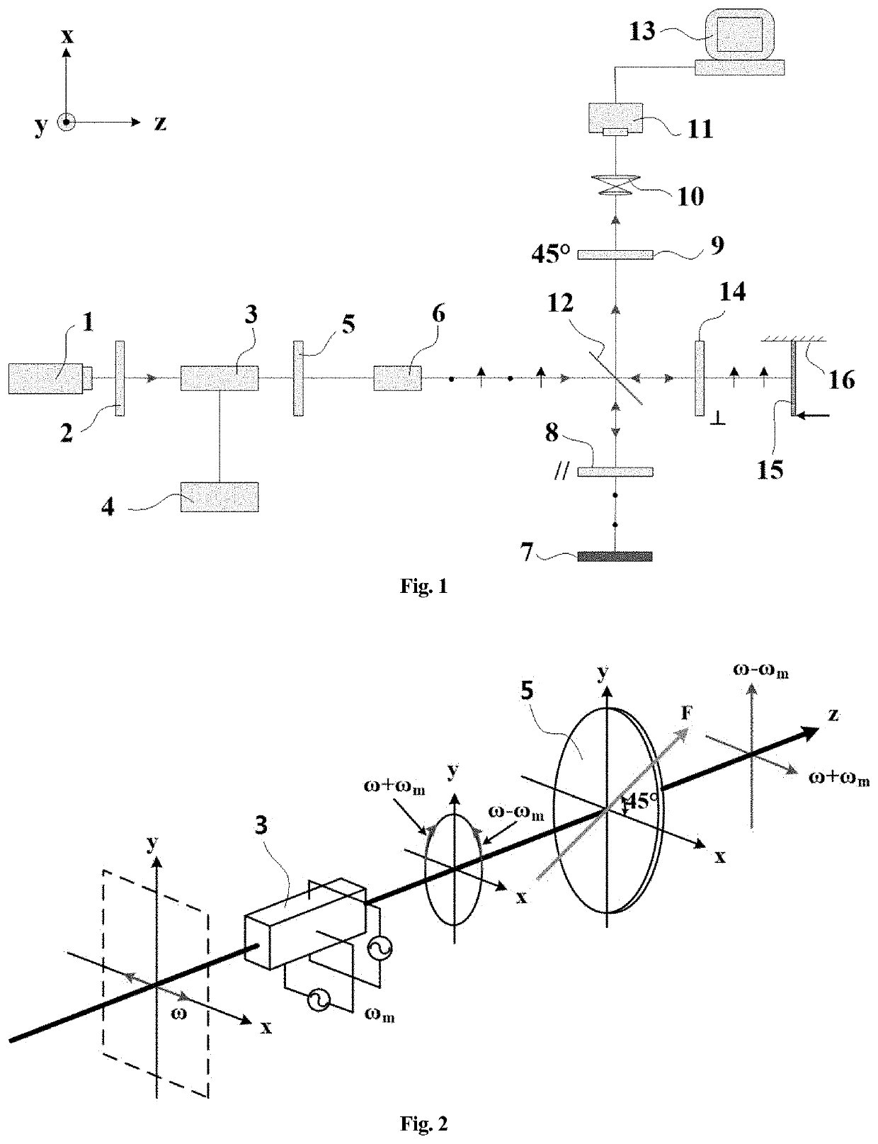
[0024]The following is a detailed description of the embodiment using the principle of the laser Doppler imaging full-field measurement as shown in FIGS. 1 and 2. It should be emphasized that the following description is just for an example and not intended to limit the scope and application of the present invention.

[0025]As shown in FIG. 1, the reference number 1 represents by laser diodes; the reference number 28, 9 and 14 represent the polarizers; the reference number 3 represents the lithium niobate crystal (LiNbO3); the reference number 4 represents the driving power of the lithium niobate crystal; the reference number 5 represents the quarter-wave plate; the reference number 6 represents the spatial filter; the reference number 7 represents the reference object; the reference number 10 represents the imaging system; the reference number 11 represents the CCD camera; the reference number 12 represents the beam splitter; the reference number 13 represents the computer; the refer...


PUM


Abstract

A method for full-field measurement using Doppler imaging, comprising the following steps: turning on a laser and adjusting the laser; adjusting a spatial filter to obtain circular laser spots having uniform intensity distribution; adjusting a quarter-wave plate and a whole polarizer in a system, and requiring two beams in a reference object and a measured object having different frequencies and perpendicular polarization directions; applying slight pressure to the measured object, setting a charge coupled device (CCD) camera into a continuous acquisition mode, observing interference fringes, and adjusting a light path so that the fringes are clear and visible; setting the sampling frequency, sampling time, captured image format and resolution size of the CCD camera; turning on a lithium niobate crystal drive power switch to produce a heterodyne carrier frequency; applying continuous equal pushing force to the measured object by means of piezoelectric ceramics (PZT) so as to make the measured object produce continuous bending deformation; controlling the CCD camera to sample using a computer, and collecting a set of time series light interference images along with the continuous deformation of the measured object; and processing the time series light intensity interference image to obtain a three-dimensional data module comprising continuous deformation of the measured objects distributed in time and space.

Description

[0001]This is a divisional application of U.S. Ser. No. 16 / 324,181, filed on Feb. 8, 2019, titled Method for Full-Field Measurement Using Dynamic Laser Doppler Imaging.FIELD OF THE INVENTION[0002]The present invention relates to a method for measuring a full-field by dynamic laser Doppler imaging, which belongs to the technical field of optical laser measurement.PRIOR ART[0003]It is a laser that makes a Doppler effect in acoustics develop into the field of optics. The laser Doppler effect is an effective method for deformation measurement. However, due to the restriction of the detector response frequency, the system can't directly measure the optical signal. Thus, the optical frequency difference technique must be applied to extract the deformation information from the low frequency interference signal. Combining optical Doppler effect with optical heterodyne interferometry, the so-called laser Doppler technology in the existing technology is formed.[0004]Laser Doppler technology h...

Claims


Application Information

Patent Timeline
IPC IPC(8): G01B9/02H01S3/10
CPCG01B9/02045H01S3/10053G01B9/02084G01B2290/70G01B9/02003
Inventor GAO, ZHANQIN, JIEFENG, QIBOWANG, SHENGJIAWANG, XUYANG, SHANWEIGAO, CHENJIA
Owner BEIJING JIAOTONG UNIV
Why Eureka
Try Eureka