
Ionic conductor and electricity storage device

a technology of ionic conductor and electricity storage device, which is applied in the field of ionic conductor, can solve the problems of low level relatively low lithium ion conductivity of molded powder products, and achieve the effects of preventing deterioration in capacity, high lithium ion conductivity, and effective enhancement of close contact between particles

Pending Publication Date: 2021-04-08
NGK SPARK PLUG CO LTD
View PDF0 Cites 0 Cited by
  • Summary
  • Abstract
  • Description
  • Claims
  • Application Information

AI Technical Summary

Benefits of technology

The patent describes an ion conductor that improves the conductivity of lithium ions by combining an oxide-type lithium ion conductor with a complex hydride. The complex hydride enhances the close contact between particles in the powder, resulting in high ion conductivity when formed into a tightly compacted product. The ion conductor contains no sulfide-type ion conductor, which may produce harmful gas. The patent also discusses the use of the ion conductor in solid electrolyte layers, cathodes, and anodes of electricity storage devices, where its lithium ion conductivity can be significantly improved.

Problems solved by technology

However, since the oxide-type lithium ion conductor in powder form is relatively hard, the molded product of the powder exhibits a low level of close contact between particles and relatively low lithium ion conductivity.

Method used


Image

  • Ionic conductor and electricity storage device
  • Ionic conductor and electricity storage device
  • Ionic conductor and electricity storage device

Examples


embodiment

A. Embodiment

A-1. Structure of Complete-Solid Battery 102:

(Entire Structure)

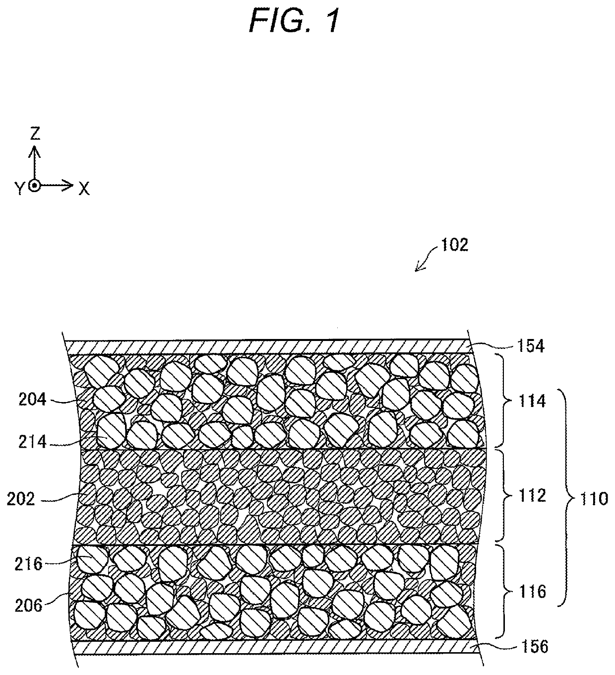
[0025]FIG. 1 is an explanatory view schematically showing a cross section of a complete-solid lithium ion secondary battery (hereinafter will be referred to as “complete-solid battery”) 102 according to the present embodiment. FIG. 1 shows mutually orthogonal X-axis, Y-axis, and Z-axis for specifying respective directions. In the present specification, for the sake of convenience, the positive Z-axis direction is called the “upward direction,” and the negative Z-axis direction is called the “downward direction.”

[0026]The complete-solid battery 102 includes a battery body 110, a cathode-side collector member 154 disposed on one side (upper side) of the battery body 110, and an anode-side collector member 156 disposed on the other side (lower side) of the battery body 110. Each of the cathode-side collector member 154 and the anode-side collector member 156 is an electrically conductive member having an approx...


PUM


Abstract

Provided is an ionic conductor with which adhesion between particles can be enhanced simply by pressure-molding a powder without using sulfide ionic conductors and without performing firing or vapor deposition, and which can exhibit a high lithium ionic conductivity. This ionic conductor contains, in addition to an oxide lithium ionic conductor, a complex hydride.

Description

CROSS-REFERENCE TO RELATED PATENT APPLICATIONS[0001]This application is a U.S. National Phase Application under 35 U.S.C. § 371 of International Patent Application No. PCT / JP2019 / 017195 filed on Apr. 23, 2019 and claims the benefit of priority to Japanese Patent Applications No. 2018-088495 filed on May 2, 2018, all of which are incorporated herein by reference in their entireties. The International Application was published in Japanese on Nov. 7, 2019 as International Publication No. WO / 2019 / 212007 under PCT Article 21(2).FIELD OF THE INVENTION[0002]The technique disclosed in the present specification relates to an ionic conductor.BACKGROUND OF THE INVENTION[0003]In recent years, an increasing demand has arisen for high-performance electricity storage devices in association with, for example, the prevalence of electronic apparatuses (e.g., personal computers and cellular phones) and electric-powered automobiles, and the growing use of natural energy such as sunlight or wind power. ...

Claims


Application Information

Patent Timeline
IPC IPC(8): H01M10/0562H01M4/13H01M4/62H01M10/0525H01M12/02
CPCH01M10/0562H01M4/13H01M2300/0071H01M10/0525H01M12/02H01M4/62H01B1/06H01B1/08H01G11/06H01G11/56H01G11/50H01M10/052H01M12/08H01G11/38H01M2220/30H01M2220/20C01B6/21Y02T10/70
Inventor TAKEUCHI, YUKIUCHIDA, MANATOIGA, YUTASHISHIHARA, DAISUKEHIKOSAKA, HIDEAKIMIZUTANI, HIDETOSHI
Owner NGK SPARK PLUG CO LTD
Learn More