Positive Electrode for Lithium Ion Battery and Lithium Ion Battery Using Same
a lithium ion battery and positive electrode technology, applied in the direction of lead-acid accumulators, cell components, electrochemical generators, etc., can solve the problems of battery performance reduction, oxidative decomposition of electrolyte becomes a problem, etc., and achieve high lithium ion conductivity, reduce the effect of lithium ion conductivity and high moisture resistan
- Summary
- Abstract
- Description
- Claims
- Application Information
AI Technical Summary
Benefits of technology
Problems solved by technology
Method used
Image
Examples
first exemplary embodiment
[0019] In the first exemplary embodiment, an inorganic compound with lithium ion conductivity expressed by general formula (1) is used as a cover layer of a positive electrode active material layer.
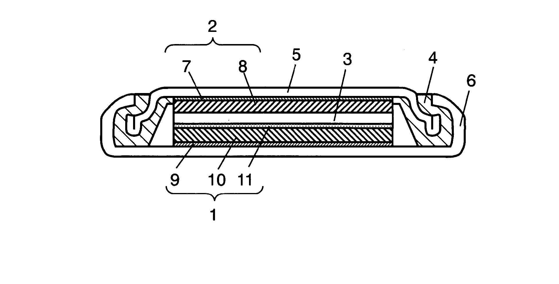
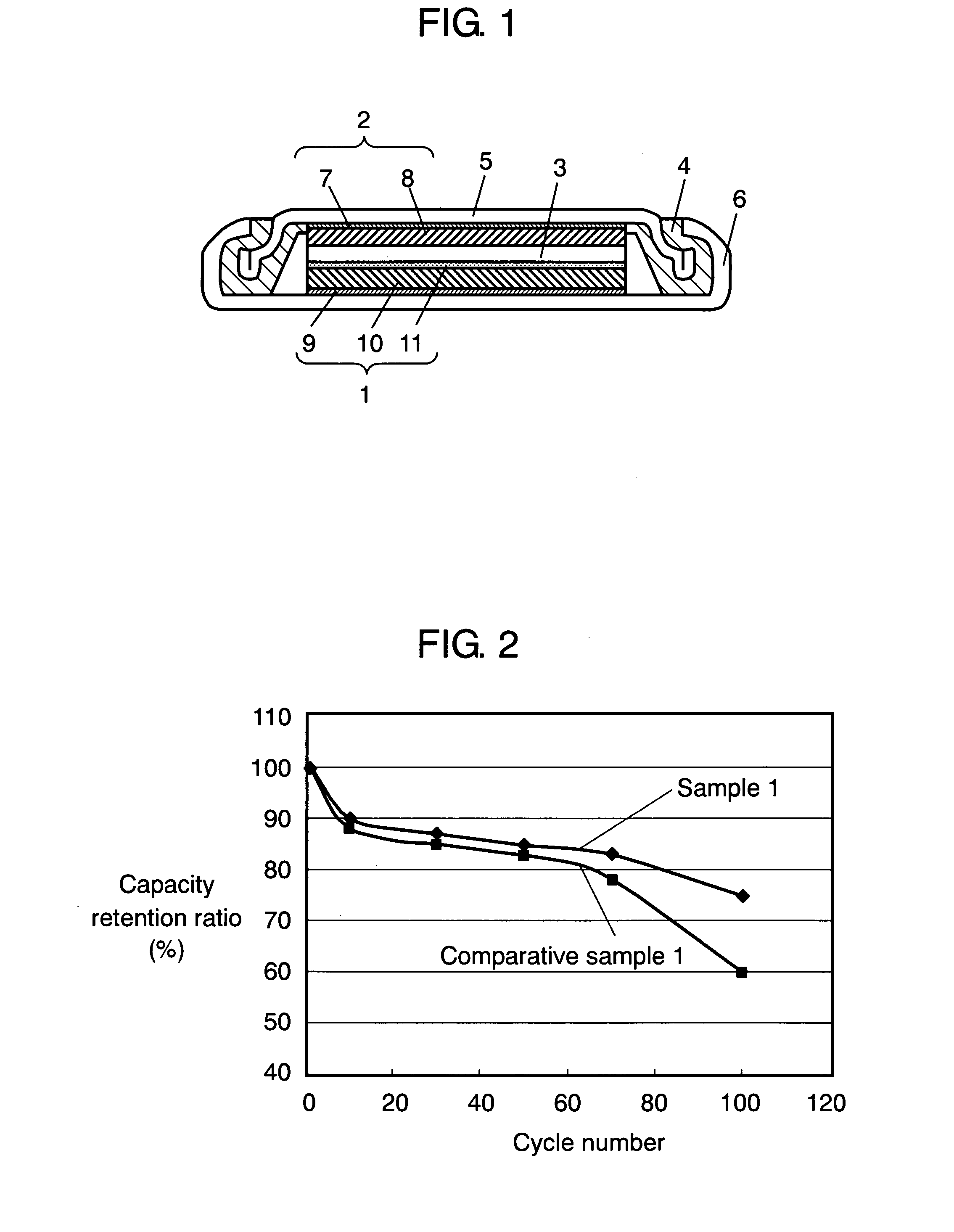
[0020]FIG. 1 is a schematic sectional view of a coin battery using a positive electrode in accordance with the first exemplary embodiment. The battery has positive electrode 1, negative electrode 2 that faces positive electrode 1 and releases lithium ions during discharge, and electrolyte 3 that is interposed between positive electrode 1 and negative electrode 2 and conducts lithium ions. Positive electrode 1 and negative electrode 2 are accommodated along with electrolyte 3 in case 6 using gasket 4 and lid 5.
[0021] Negative electrode 2 is composed of negative electrode collector 7 and negative electrode active material layer 8 that is disposed on negative electrode collector 7 and includes negative electrode active material. Lid 5 may also serve as negative electrode collector 7.
[0022...
example 1
[0052] Active material layer 10 is formed on collector 9 made of gold foil, and cover layer 11 having the chemical composition expressed by LixPTyOz is formed on active material layer 10 as following way.
[0053] In samples 1 through 9, active material layer 10 made of 3-μm thick LiCoO2 as the active material is formed on collector 9 made of 20-μm thick gold foil by the rf magnetron sputtering method. At this time, using LiCoO2 with a diameter of 4 inches as a target, the sputtering is performed for 2 hours at an rf power of 200 W in argon atmosphere of 20 mTorr. Then, firing is performed at 800° C. for 5 hours in the air using a firing furnace to produce desired active material layer 10. The composition of produced active material layer 10 is determined by measuring a sample by the inductive coupled high-frequency plasma spectral analysis method (ICP spectral analysis method). Here, the sample has been produced by disposing a platinum plate beside collector 9 in producing active mat...
example 2
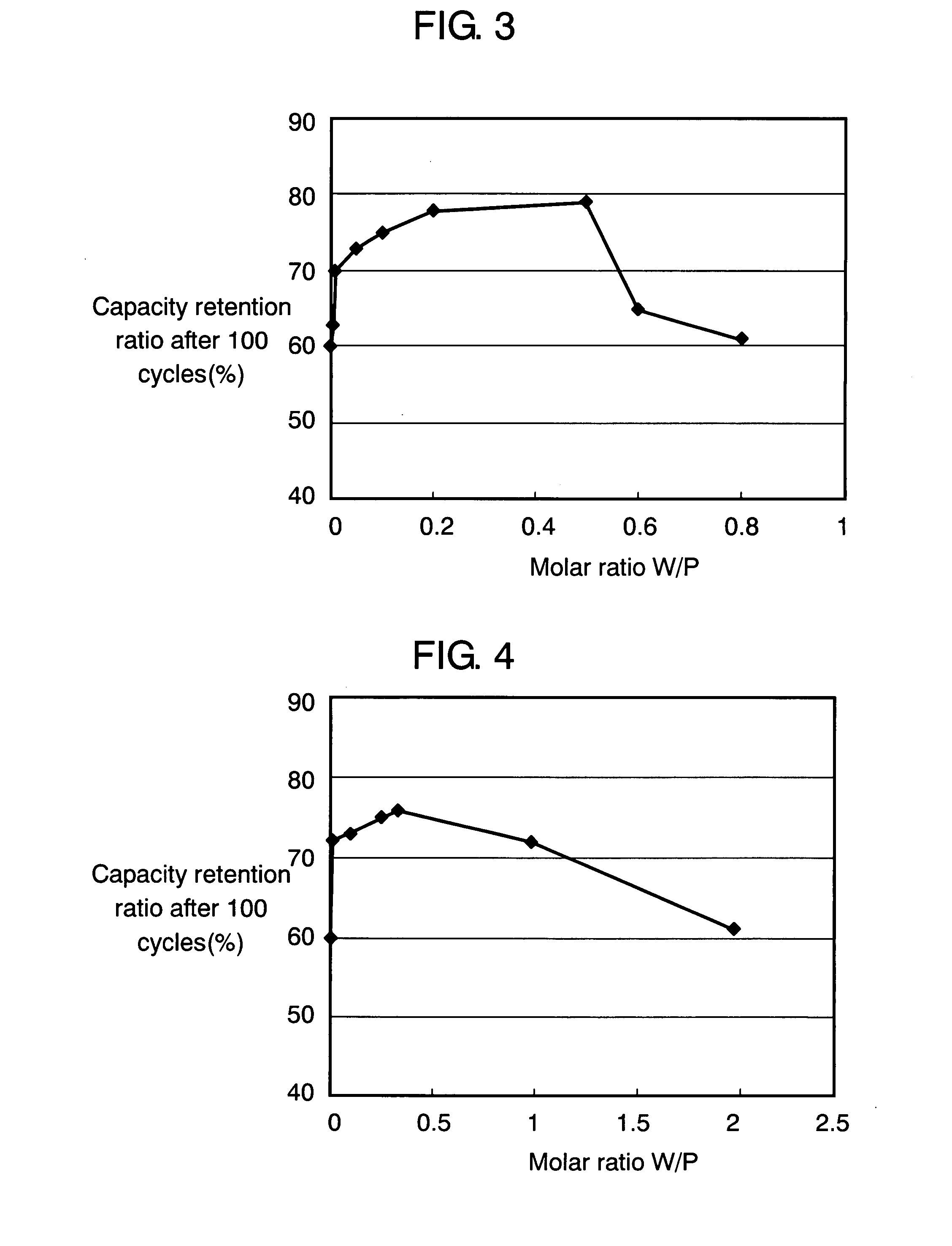
[0066] Next, the result of examining the range of value y in formula LixPTyOz is described. Here, as an example, a case where tungsten (W) is used as transition metal element T is described.
[0067] As shown in Table 2, samples 1A through 1H are produced. In producing these samples, each cover layer 11 having composition LixPWyOz of a different molar ratio of W to P (referred to as “W / P”) is formed while the sputtering rf power is varied in the structure of sample 1. Value W / P corresponds to y in the composition formula. Other conditions are the same as in sample 1. Values W / P in samples 1A through 1H are 0.005, 0.01, 0.05, 0.1, 0.2, 0.5, 0.6, and 0.8.
TABLE 2Sampley1A0.0051B0.011C0.051D0.11E0.21F0.51G0.61H0.8Comparative0sample 1
[0068] Using these samples, batteries are produced and evaluated similarly to example 1. FIG. 3 illustrates the relationship between the capacity retention ratio and W / P at the 100th cycle. This relationship is obtained when charge / discharge is performed on ...
PUM
| Property | Measurement | Unit |
|---|---|---|
| thickness | aaaaa | aaaaa |
| diameter | aaaaa | aaaaa |
| thickness | aaaaa | aaaaa |
Abstract
Description
Claims
Application Information
 - R&D
- Intellectual Property
- Life Sciences
- Materials
- Tech Scout
- Unparalleled Data Quality
- Higher Quality Content
- 60% Fewer Hallucinations
Browse by: Latest US Patents, China's latest patents, Technical Efficacy Thesaurus, Application Domain, Technology Topic, Popular Technical Reports.
© 2025 PatSnap. All rights reserved.Legal|Privacy policy|Modern Slavery Act Transparency Statement|Sitemap|About US| Contact US: help@patsnap.com


