
Processing apparatus, sysyem, x-ray measurement method, and program

a processing apparatus and semiconductor technology, applied in the field of photoncounting type semiconductor detector processing apparatus, can solve the problems of insufficient correction accuracy, pulse signal cannot be counted, and count loss thereof, so as to reduce the influence of count loss

Active Publication Date: 2021-04-29
RIGAKU CORP
View PDF0 Cites 1 Cited by
  • Summary
  • Abstract
  • Description
  • Claims
  • Application Information

AI Technical Summary

Benefits of technology

The present invention aims to provide a processing apparatus capable of reducing influence of count loss on a higher count rate that has not been able to be covered by a conventional method. The processing apparatus uses a semiconductor detector that is capable of exposing in a short period and in a short unit time. This allows for easy calculation of the pulse detection ratio by measuring the time during which the pulse signal is detected. The processing apparatus also calculates the apparent time constant, which is the true time constant when the pulse detection ratio is zero. This eliminates the influence of count loss when there is no overlapping of pulses and makes the model more realistic. The system performs exposure in a shorter time than the time constant of the pulse signal using the semiconductor detector, which allows for high time resolution and reduces the load of readout. The readout time is shortened due to the inability to detect three or more pulses at one exposure. Overall, the invention provides a solution for reducing influence of count loss on a higher count rate.

Problems solved by technology

However, when the next pulse signal is generated in a situation where the intensity of the pulse signal exceeds the threshold, the pulse signal cannot be counted, and thus count loss thereof occurs.
However, according to the radiation measurement device disclosed in Patent Document 1, the correction table performs correction by making a double pulse be proximate with the experimentally generated pseudo signal pulse to find the resolution time t1 of pile-up and the proximity time t2 during when the erroneous counting occurs, and thus accuracy of the correction becomes insufficient when the count rate is increased to such an extent that proximity of three or more pulses occurs frequently.
Further, according to the method disclosed in Patent Document 2, the dead time is constant with respect to increase of the count rate, and thus accuracy of the correction becomes insufficient with increase of the count rate.

Method used


Image

  • Processing apparatus, sysyem, x-ray measurement method, and program
  • Processing apparatus, sysyem, x-ray measurement method, and program
  • Processing apparatus, sysyem, x-ray measurement method, and program

Examples


embodiment

(Constitution of Detection System)

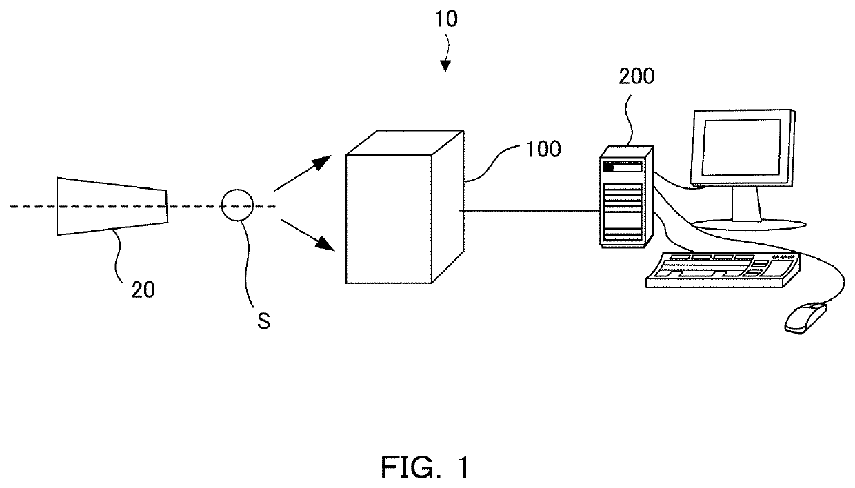
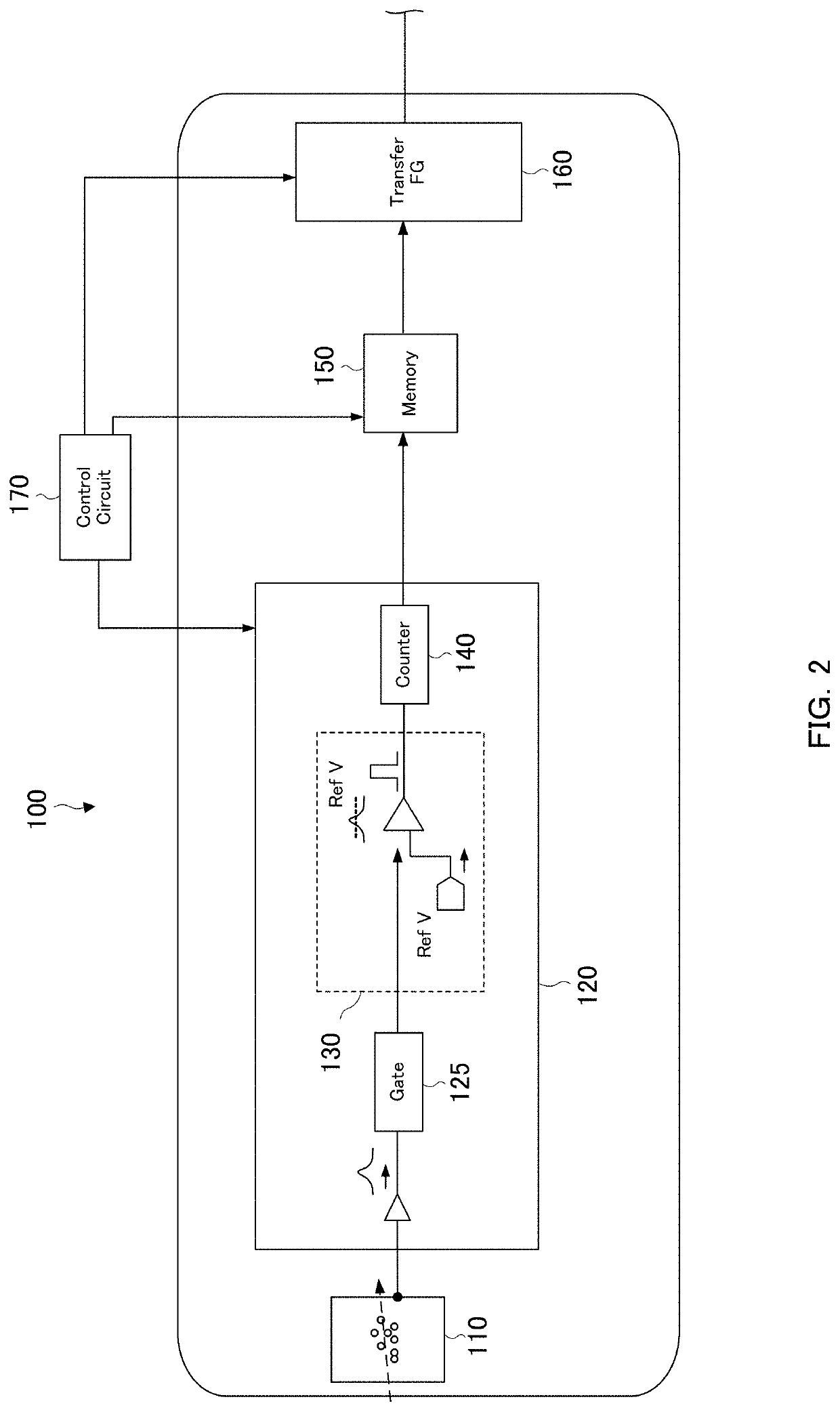
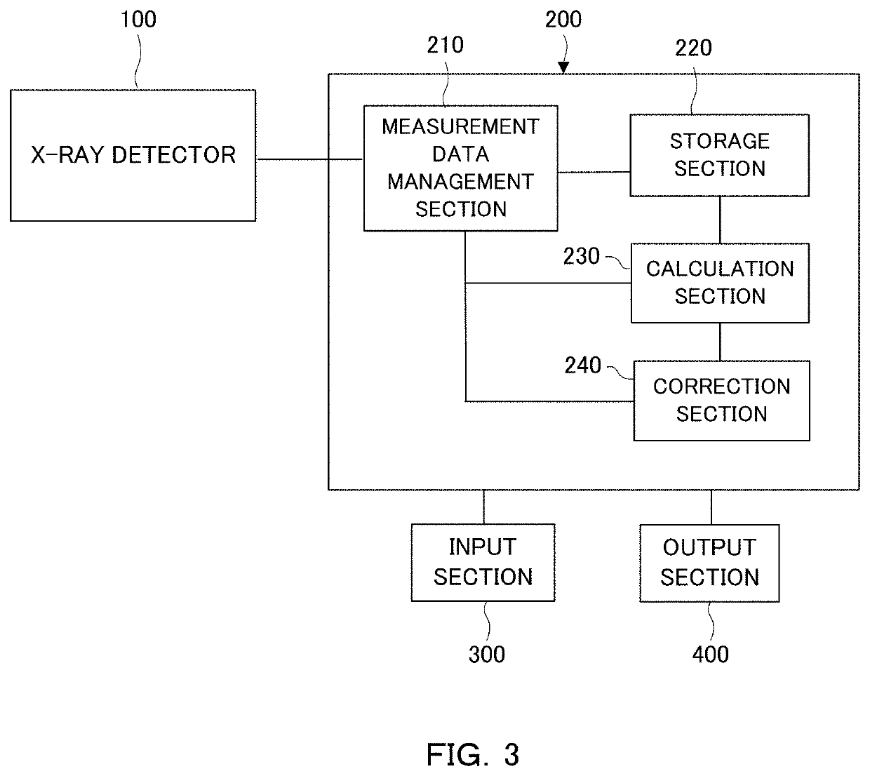
[0038]FIG. 1 is a schematic diagram showing an example of a configuration of an X-ray detection system 10. As shown in FIG. 1, the X-ray detection system 10 comprises an X-ray source 20, a sample S, an X-ray detector 100 and a processing apparatus 200.

[0039]For example, the X-ray source 20 generates X-rays by making electron flux radiated from a filament, which is a cathode, collide with a rotor target, which is an anticathode. Metal such as Mo or Cu, for example, is provided on an outer-peripheral face of the rotor target. When electrons collide with a Mo target, X-rays including MoKα rays (a wavelength of 0.711 Å), which are characteristic rays, are radiated. When electrons collide with a Cu target, X-rays including CuKα rays (a wavelength of 1.542 Å), which are characteristic rays, are radiated. X-rays radiated from the X-ray source 20 are so-called point-focus X-ray beams.

[0040]A sample S is supported by a sample support apparatus. The X-ray det...

example 1

[0087]The X-ray measurement method according to the present invention is applicable for being used with an X-ray reflectivity method. According to the X-ray reflectivity method, there is a position where an intensity of reflected X-rays is high to a position where the intensity of reflected X-rays is low. Accordingly, it is preferred that the method according to the present invention is applied for the position where the intensity is high, and a conventional method is applied for the position where the intensity is low. For example, when 40 nsec exposure is applied 100 times for measurement, and 1 msec exposure is applied once separately from that for the measurement, even though there is an in-plane intensity distribution, it is possible to acquire data at the position where the intensity is low via 1 msec exposure, and it is possible to acquire data at the position where the intensity is high via 40 nsec exposure.

[0088]There is provided a method of conducting measurements by apply...

example 2

[0089]The X-ray measurement method according to the present invention is applicable for being used in synchrotron radiation facilities such as Spring-8. In that case, the data obtained from a conventional X-ray detector attached to a radiation detector in the synchrotron radiation facilities are processed by utilizing an X-ray measurement method, a processing apparatus, or a program according to the present invention.

Other Examples

[0090]Other than those described above, according to total reflection caused by a metal complex sample, an X-ray small angle scattering method or the like out of single crystal X-ray diffraction methods, an intensity of X-rays to be measured becomes high, and thus it is suitable to use an X-ray measurement method according to the present invention.

(Simulation)

[0091]A comparison of the X-ray measurement method according to the present invention with a method of counting Rising Edge was simulated from computer experiment. FIG. 11 is a schematic diagram showi...


PUM

PropertyMeasurementUnit
energyaaaaaaaaaa
time constantaaaaaaaaaa
exposure timeaaaaaaaaaa

Abstract

There are provided a storage section 220 that stores an output value read out by counting a pulse signal of incident X-rays, by a photon-counting type semiconductor detector; and a calculation section 230 that calculates a count value based on the output value that has been read out, wherein the calculation section 230 uses a model in which an apparent time constant of the pulse signal monotonously decreases against increase in pulse detection ratio with respect to exposure. According to such a model, the corresponding apparent time constant is able to be obtained even in any higher count rate. As a result of this, reduced can be the influence of count loss even on the count rate that has not been able to be covered by the conventional method.

Description

TECHNICAL FIELD[0001]The present invention relates to a processing apparatus with a photon-counting type semiconductor detector, and to a system, an X-ray measurement method and a program thereof.RELATED ART[0002]The photon-counting type semiconductor detector used for a radiation measurement measures an intensity of X-rays by counting the number of times when an intensity of a pulse signal detected in a predetermined time exceeds a threshold, as the number of pulse signals. However, when the next pulse signal is generated in a situation where the intensity of the pulse signal exceeds the threshold, the pulse signal cannot be counted, and thus count loss thereof occurs. When the intensity of X-rays is too high, the count loss occurs frequently, and the measured intensity of X-rays is consequently estimated to be lower than the actual intensity of X-rays.[0003]A method of correcting the measured count value has been investigated as a method of reducing influence of count loss like th...

Claims


Application Information

Patent Timeline
Patent Type & Authority Applications(United States)
IPC IPC(8): G01T1/24G01T1/17G01T1/166
CPCG01T1/247G01T1/1663G01T1/171G01T1/18G01T1/24
Inventor KOBAYASHI, SHINTARONAKAE, YASUKAZUSAKUMURA, TAKUTOSAKUMA, YASUTAKA
Owner RIGAKU CORP
Learn More