
Catalyst and process of upgrading heavy oil in the presence of steam

a technology of heavy oil and catalyst, which is applied in the field of hydrocarbon processing, can solve the problems of reducing the efficiency of cracking and upgrading heavy hydrocarbon residua, affecting the efficiency of hydrocarbon oil refining, etc., so as to facilitate the addition of hydrogen and oxygen radicals, reduce asphaltenes, and reduce water dissociation.

Active Publication Date: 2021-06-24
SAUDI ARABIAN OIL CO
View PDF0 Cites 2 Cited by
  • Summary
  • Abstract
  • Description
  • Claims
  • Application Information

AI Technical Summary

Benefits of technology

The patent text describes a method to upgrade heavy oil using a highly dispersed aqueous catalyst. The catalyst helps to reduce asphaltenes and coke formation by promoting water splitting and adding hydrogen to thermally generated hydrocarbon free radicals. The catalyst is dispersed in a submicronic scale, which increases contact time between the water, oil, and catalyst, while minimizing diffusion control. This results in improved catalyst performance at lower concentrations and reduced heat gradient build-up. Overall, the method allows for efficient upgrading of heavy oil with reduced emissions of asphaltenes and coke.

Problems solved by technology

However, the self-ionization of water is suppressed as the temperature increases which may negatively affect the efficiency of cracking and upgrading heavy hydrocarbon residua.
However, at increased temperature (such as the boiling point or the critical point) and constant pressure, such tetrahedral structure of water collapses.
Consequently, water at temperatures greater than its boiling point is miscible in a nonpolar hydrocarbon-based medium.
Because the self-ionization of water, at a constant pressure, decreases as the critical temperature is approached, it is expected that the self-splitting of water at heavy oil upgrading temperatures is improbable unless high pressures are employed.

Method used


Image

  • Catalyst and process of upgrading heavy oil in the presence of steam

Examples


example

[0092]The disclosure is illustrated by the following example, which is presented for illustrative purposes only, and is not intended as limiting the scope of the invention which is defined by the appended claims.

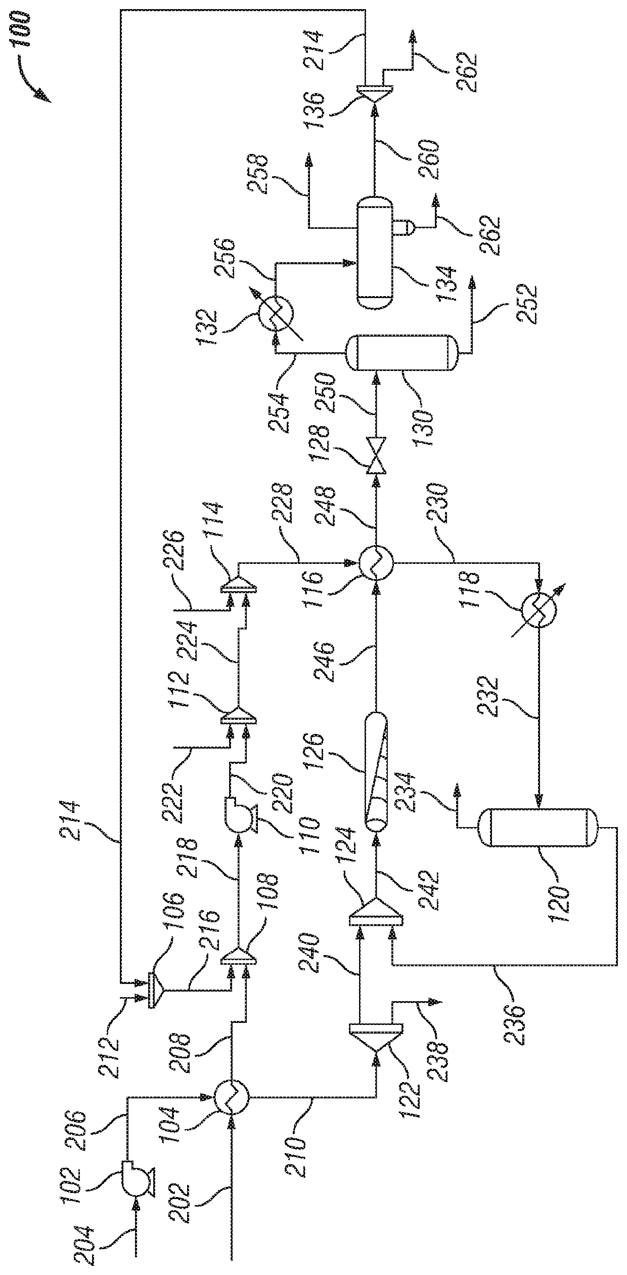
[0093]An aqueous reforming system having a configuration similar to FIGURE was modelled using the HYSYS Hydroprocessing Model (Aspen Technology, Inc., Bedford, Mass.). In reference to the properties of the streams for EXAMPLE, the description and stream numbers for FIG. 1s used.

[0094]A heavy hydrocarbon (stream 202) was introduced into the respective system at a mass flow rate of about 135,100 kg / hr. A surfactant composition (stream 212) was introduced into the respective system at a mass flow rate of about 41 kg / hr. The surfactant composition included paraffinic, naphthenic, and aromatic compounds functionalized with carboxylic acid groups. The surfactant composition included between about 15 wt. % and about 20 wt. % aromatic carboxylic acids. The surfactant composition inc...


PUM


Abstract

Embodiments of the disclosure provide an aqueous reforming system and a method for upgrading heavy hydrocarbons. A hydrocarbon feed and a surfactant stream are combined to produce a first precursor stream. The first precursor stream and an alkali feed are combined to produce a second precursor stream. The second precursor stream and a transition metal feed are combined to produce a catalytic emulsion stream. The catalytic emulsion stream is heated to produce a catalytic suspension and a decomposition gas, where the decomposition gas is separated by a first separator. The catalytic suspension is combined with a preheated water stream to produce an aqueous reformer feed. The aqueous reformer feed is introduced to an aqueous reformer such that the heavy hydrocarbons undergo conversion reactions to produce an effluent stream. The effluent stream is introduced to a second separator to produce a heavy stream and a light stream. The light stream is introduced to a third separator to produce a gas stream, a distillate stream, and a spent water stream. Optionally, a portion of the distillate stream and the hydrocarbon feed can be combined to produce the first precursor stream such that the first precursor stream is in the absence of a surfactant.

Description

BACKGROUNDField of the Disclosure[0001]Embodiments of the disclosure generally relate to hydrocarbon processing. More specifically, embodiments of the disclosure relate to a method and system for utilizing a catalyst for aqueous reforming to process hydrocarbons.Description of the Related Art[0002]Water is commonly used in non-catalytic steam cracking reactions such as aquathermolysis. Water is an amphoteric compound capable of acting as an acid or base in acid or base catalysis. The self-ionization of water can be exploited in these processes to saturate free radicals of produced hydrocarbons. However, the self-ionization of water is suppressed as the temperature increases which may negatively affect the efficiency of cracking and upgrading heavy hydrocarbon residua. Water molecules self-dissociate into hydronium and hydroxide ions at any given temperature and pressure according to the following equilibrium reaction:2H2O(l)↔OH−(aq)+H3O+(aq).[0003]The extent of self-ionization of wa...

Claims


Application Information

Patent Timeline
IPC IPC(8): C10G47/02C10G47/32C10G47/36
CPCC10G47/02C10G47/32C10G47/36C10G2300/805C10G2300/4012C10G2300/107C10G2400/04C10G2300/4006C10G2300/1077C10G31/06C10G31/08C10G11/20C10G11/02C10G19/02
Inventor FATHI, MAZIN M.CHOI, KI-HYOUKALDOSSARY, MOHAMMED R.
Owner SAUDI ARABIAN OIL CO
Learn More